VN16B(011Y) STMicroelectronics, VN16B(011Y) Datasheet
VN16B(011Y)
Specifications of VN16B(011Y)
Available stocks


Related parts for VN16B(011Y)


VN16B(011Y) Summary of contents
Page 1
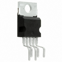
... °C for a battery voltage which does not activate self protection. Table 2. Order Codes Package PENTAWATT Vert. PENTAWATT Hor. PENTAWATT In line June 2004 Figure 1. Package ( 5 85°C c PENTAWATT Technology, Tube VN16B VN16B(011Y) VN16B(012Y) VN16B PENTAWATT (vertical) (horizontal) PENTAWATT (in-line) Tape and Reel - - - REV. 2 1/14 ...
Page 2
VN16B Figure 2. Block Diagram Table 3. Absolute Maximum Ratings Symbol V Drain-Source Breakdown Voltage (BR)DSS I Output Current (cont OUT I (RMS) RMS Output Current at T OUT I Reverse Output Current Input ...
Page 3
Figure 3. Connection Diagram Figure 4. Current and Voltage Conventions Table 4. Thermal Data Symbol R Thermal Resistance Junction-case thj-case R Thermal Resistance Junction-ambient thj-amb Parameter Max Max VN16B Value Unit 1.5 °C/W 60 °C/W 3/14 ...
Page 4
VN16B ELECTRICAL CHARACTERISTICS < -40 ≤ T ≤ 125 °C unless otherwise specified) (8 < Table 5. Power Symbol Parameter V Supply Voltage CC (3) Nominal Current State Resistance on I ...
Page 5
ELECTRICAL CHARACTERISTICS (cont’d) Table 8. Protections and Diagnostics Symbol Parameter Status Voltage Output Low V STAT V Under Voltage Shut Down USD Status Clamp Voltage V SCL T Thermal Shut-down Temperature TSD T Thermal Shut-down Hysteresis SD(hyst.) T Reset Temperature ...
Page 6
VN16B Figure 7. Switching Time Waveforms FUNCTIONAL DESCRIPTION The device has a diagnostic output which indicates open load in on-state, open load in off- state, over temperature conditions and stuck- From the falling edge of the ...
Page 7
Table 9. Truth Table Normal Operation Over-temperature Under-voltage Short load Open Load Note: 8. With an additional external resistor. Figure 8. Waveforms Input Output ...
Page 8
VN16B Figure 9. Over Current Test Circuit Figure 10. Typical Application Circuit With A Schottky Diode For Reverse Supply Protection 8/14 ...
Page 9
Figure 11. Typical Application Circuit With Separate Signal Ground VN16B 9/14 ...
Page 10
VN16B PACKAGE MECHANICAL Table 10. PENTAWATT (vertical) Mechanical Data Symbol Dia. Figure 12. PENTAWATT (vertical) Package Dimensions Note: Drawing is not to scale. 10/14 ...
Page 11
Table 11. PENTAWATT (horizontal) Mechanical Data Symbol Dia. Figure 13. PENTAWATT (horizontal) Package Dimensions Note: Drawing is not to scale. millimeters Min ...
Page 12
VN16B Table 12. PENTAWATT (in-line) Mechanical Data Symbol Dia. Figure 14. PENTAWATT (in-line) Package Dimensions Note: Drawing is not to scale. 12/14 millimeters Min ...
Page 13
REVISION HISTORY Table 13. Revision History Date Revision September-1994 1 18-June-2004 2 Description of Changes First Issue Stylesheet update. No content change. VN16B 13/14 ...
Page 14
... No license is granted by implication or otherwise under any patent or patent rights of STMicroelectronics. Specifications mentioned in this publication are subject to change without notice. This publication supersedes and replaces all information previously supplied. STMicroelectronics products are not authorized for use as critical components in life support devices or systems without express written approval of STMicroelectronics ...