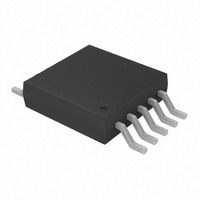
TC664EUN Microchip Technology, TC664EUN Datasheet - Page 19

TC664EUN
Manufacturer Part Number
TC664EUN
Description
IC PWM FAN SPEED CTRLR 10-MSOP
Manufacturer
Microchip Technology
Type
Controller - SMBus Fan Speedr
Datasheet
1.TC664EUN.pdf
(36 pages)
Specifications of TC664EUN
Applications
Fan Controller, Brushless (BLDC)
Number Of Outputs
1
Voltage - Supply
3 V ~ 5.5 V
Operating Temperature
-40°C ~ 85°C
Mounting Type
Surface Mount
Package / Case
10-MSOP, Micro10™, 10-uMAX, 10-uSOP
Motor Type
PWM
No. Of Outputs
1
Output Current
5mA
Output Voltage
4.4V
Supply Voltage Range
3V To 5.5V
Driver Case Style
MSOP
No. Of Pins
10
Operating Temperature Range
-40°C To +85°C
Product
Fan / Motor Controllers / Drivers
Operating Supply Voltage
3 V to 5.5 V
Supply Current
300 uA
Mounting Style
SMD/SMT
Rohs Compliant
Yes
Lead Free Status / RoHS Status
Lead free / RoHS Compliant
Current - Output
-
Voltage - Load
-
Lead Free Status / Rohs Status
Lead free / RoHS Compliant
Available stocks
Company
Part Number
Manufacturer
Quantity
Price
Company:
Part Number:
TC664EUN
Manufacturer:
MICROCHIP
Quantity:
12 000
Part Number:
TC664EUN
Manufacturer:
MICROCHIP/微芯
Quantity:
20 000
Company:
Part Number:
TC664EUNTR
Manufacturer:
MICROCHIP
Quantity:
12 000
6.3
The Configuration Register is an 8-bit, read/writable,
multi-function control register. This register allows the
user to clear fan faults, select RPM resolution, select
REGISTER 6-3:
2002 Microchip Technology Inc.
CONFIGURATION REGISTER
(CONFIG)
bit 7
bit 6
bit 5
bit 4
bit 3
bit 2-1
bit 0
CONFIGURATION REGISTER (CONFIG)
bit 7
FFCLR: Fan Fault Clear
1 = Clear Fan Fault, this will reset the Fan Fault bit in the Status Register and the FAULT out-
0 = Normal Operation (default)
RES: Resolution Selection for RPM Output Register
1 = RPM Output Register (RPM) will be set for 25 RPM (9-bit) resolution.
0 = RPM Output Register (RPM) will be set for 50 RPM (8-bit) resolution. (default)
DUTYC: Duty-Cycle Control Method
1 = The V
0 = The V
Unimplemented: Read as '0'
Unimplemented: Read as '1'
FPPR: Fan Pulses Per Rotation
The TC664/TC665 device uses this setting to understand how many current pulses per revolu-
tion the fan should have. It then uses this as part of the calculation for the fan RPM value for
the RPM Register. See Section 7.7 for application information on determining your fan’s
number of current pulses per revolution.
00 = 1
01 = 2 (default)
10 = 4
11 = 8
SDM: Shutdown Mode
1 = Shutdown Mode. See Section 4.9 for more information on low power shutdown mode.
0 = Normal Operation. (default)
Legend:
R = Readable bit
-n = Value at POR
FFCLR
R/W-0
put.
duty-cycle will be taken from the duty-cycle register (DUTY_CYCLE).
value will be between 30% and 100% for V
the V
(default)
IN
OUT
OUT
pin is open when this mode is selected, the V
R/W-0
RES
duty-cycle will be controlled via the SMBus interface. The value for the V
duty-cycle will be controlled via the V
DUTYC
R/W-0
W = Writable bit
’1’ = Bit is set
U-0
—
V
fan current pulses per rotation for the fan (for fan RPM
calculation) and put the TC664/TC665 device into a
shutdown mode to reduce power consumption. See
Register 6-3 below for the Configuration Register bit
descriptions.
OUT
duty cycle (fan speed) control method, select the
IN
U = Unimplemented bit
’0’ = Bit is cleared
values between 1.62 V and 2.6 V typical. If
U-1
—
IN
analog input pin. The V
OUT
TC664/TC665
duty-cycle will default to 39.33%.
R/W-0
FPPR
x = Bit is unknown
R/W-1
FPPR
DS21737A-page 19
OUT
duty-cycle
R/W-0
SDM
OUT
bit 0


