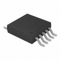
TC654EUN Microchip Technology, TC654EUN Datasheet - Page 23

TC654EUN
Manufacturer Part Number
TC654EUN
Description
IC PWM FAN SPEED CTRLR 10-MSOP
Manufacturer
Microchip Technology
Type
High Speed PWM Controllerr
Datasheet
1.TC654EUN.pdf
(36 pages)
Specifications of TC654EUN
Number Of Outputs
1
Package / Case
10-MSOP, Micro10™, 10-uMAX, 10-uSOP
Applications
Fan Controller, Brushless (BLDC)
Voltage - Supply
3 V ~ 5.5 V
Operating Temperature
-40°C ~ 85°C
Mounting Type
Surface Mount
Output Current
5 mA (Min)
Operating Supply Voltage
3 V to 5.5 V
Maximum Operating Temperature
+ 85 C
Minimum Operating Temperature
- 40 C
Mounting Style
SMD/SMT
Motor Type
PWM
No. Of Outputs
1
Output Voltage
4.4V
Supply Voltage Range
3V To 5.5V
Driver Case Style
MSOP
No. Of Pins
10
Operating Temperature Range
-40°C To +85°C
Rohs Compliant
Yes
Lead Free Status / RoHS Status
Lead free / RoHS Compliant
Current - Output
-
Voltage - Load
-
Lead Free Status / Rohs Status
Lead free / RoHS Compliant
Available stocks
Company
Part Number
Manufacturer
Quantity
Price
Part Number:
TC654EUN
Manufacturer:
MIC
Quantity:
20 000
Part Number:
TC654EUNTR
Manufacturer:
MICROCHIP/微芯
Quantity:
20 000
7.3
As discussed in previous sections, the V
has a range of 1.62 V to 2.6 V (typical), which repre-
sents a duty cycle range on the V
100%, respectively. The V
as representing temperatures. The 1.62 V level is the
low temperature at which the system only requires 30%
fan speed for proper cooling. The 2.6 V level is the high
temperature, for which the system needs maximum
cooling capability. Therefore, the fan needs to be at
100% speed.
One of the simplest ways of sensing temperature over
a given range is to use a thermistor. By using an NTC
thermistor as shown in Figure 7-3, a temperature vari-
ant voltage can be created.
FIGURE 7-3:
Circuit.
Figure 7-3 represents a temperature dependent volt-
age divider circuit. R
R
allel resistor combination that will be referred to as
R
increases, the value of R
R
V
desired relationship for the V
R
work. Figure 7-4 shows an example of this.
There are many values that can be chosen for the NTC
thermistor. There are also thermistors which have a lin-
ear resistance instead of logarithmic, which can help to
eliminate R
then a larger value thermistor should be chosen. The
voltage at the V
age output temperature sensor device. The key is to
get the desired V
temperature relationship.
The following equations apply to the circuit in
Figure 7-3.
IN
1
TEMP
TEMP
1
2002 Microchip Technology Inc.
and R
is to help linearize the response of the sensing net-
increases as temperature increases, giving the
(R
will decrease with it. Accordingly, the voltage at
Temperature Sensor Design
2
TEMP
are standard resistors. R
R
1
t
. If less current draw from V
= R
IN
IN
pin can also be generated by a volt-
1
voltage to system (or component)
t
* R
is a conventional NTC thermistor,
Temperature Sensing
t
/ R
V
t
IN
DD
decreases and the value of
1
voltages can be thought of
R
R
+ R
I
IN
1
2
DIV
input. The purpose of
t
). As the temperature
OUT
1
and R
output of 30% to
IN
V
DD
IN
analog input
t
form a par-
is desired,
EQUATION
In order to solve for the values of R
for V
need to be selected. The variables, t1 and t2, represent
the selected temperatures. The value of the thermistor
at these two temperatures can be found in the ther-
mistor data sheet. With the values for the thermistor
and the values for V
from which the values for R
Example: The following design goals are desired:
• Duty Cycle = 50% (V
• Duty Cycle = 100% (V
Using a 100 k thermistor (25°C value), we look up the
thermistor values at the desired temperatures:
• R
• R
Substituting these numbers into the given equations,
we come up with the following numbers for R
• R
• R
FIGURE 7-4:
V
Figure 7-4 graphs three parameters versus tempera-
ture. They are R
described earlier, you can see that the thermistor has a
logarithmic resistance variation. When put in parallel
with R
more linear, which is the desired effect. This gives us
the linear looking curve for V
IN
(t1) = 30°C
ture (t2) = 60°C
, And R
t
t
1
2
IN
= 79428
= 22593
140000
120000
100000
= 34.8 k
= 14.7 k
80000
60000
40000
20000
1
and the temperatures at which they are to occur
, though, the combined resistance becomes
0
TEMP
R
TEMP
V t1
V t2
@ 30°C
@ 60°C
t
, R
Vary With Temperature.
TC654/TC655
Temperature (ºC)
IN
=
=
1
How Thermistor Resistance,
, you now have two equations
IN
V
in parallel with R
--------------------------------------- -
R
--------------------------------------- -
R
IN
IN
TEMP
TEMP
Voltage
= 1.9 V) with Temperature
= 2.6 V) with Tempera-
V
V
1
D D
D D
IN
and R
NTC Thermistor
100K @ 25ºC
.
t1
t2
R
R
1
+
+
2
2
2
and R
DS21734A-page 23
R
R
can be found.
2
2
t
, and V
2
, the values
4.000
3.500
3.000
2.500
2.000
1.500
1.000
0.500
0.000
1
and R
IN
. As
2
.


