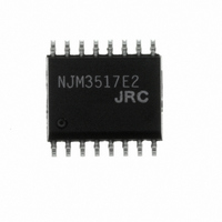
NJM3517E2# NJR, NJM3517E2# Datasheet - Page 9

NJM3517E2#
Manufacturer Part Number
NJM3517E2#
Description
IC STEPPER MOTOR CTRLR/DVR 16EMP
Manufacturer
NJR
Datasheet
1.NJM3517D2.pdf
(12 pages)
Specifications of NJM3517E2#
Applications
Stepper Motor Driver, 2 Phase
Number Of Outputs
1
Current - Output
±350mA
Voltage - Load
10 V ~ 40 V
Voltage - Supply
4.75 V ~ 5.25 V
Operating Temperature
-20°C ~ 125°C
Mounting Type
Surface Mount
Package / Case
16-EMP
Lead Free Status / RoHS Status
Lead free / RoHS Compliant
Other names
NJM#3517E2
NJM#3517E2
NJM#3517E2
Available stocks
Company
Part Number
Manufacturer
Quantity
Price
Figure 12. Diode turn-off circuit
Figure 15. Power return turn-off circuit
The pulse diagrams, figures 7 through 10, show the necessary input signals and the resulting output signals for
each drive mode.
position marked “C.”
within specifications.
1. Never disconnect ICs or PC-boards when power is supplied.
2. If second supply is not used, disconnect and leave open V
3. Remember that excessive voltages might be generated by the motor, even though clamping diodes are used.
4. Choice of motor. Choose a motor that is rated for the current you need to establish desired torque. A high
5. Never use L
6. Avoid V
On the left side are the input and output signals, the next column shows the state of each signal at the cursor
STEP is shown with a 50% duty cycle, but can, of course, be with any duty cycle, as long as pulse time (t
P
L
INPUT AND OUTPUT SIGNALS FOR DIFFERENT DRIVE MODES
USER HINTS
A
A
diodes (D1, D2) with a straight connection.
supply voltage will gain better stepping performance. If the motor is not specified for the V
limiting resistor will be necessary to connect in series with center tap. This changes the L/R time constant.
net. An alternative is to trigger the mono-flip-flop by taking a STEP and then externally pulling the RC pin
(12Pin) low (0V) for the desired on-time.
The common place for ground should be as close as possible to the IC’s ground pin (pin 3).
and L
and P
B
B
are displayed with high level, showing current sourcing.
MM
are displayed with low level, showing current sinking.
and V
A
or L
SS
B
i
power supplies with serial diodes (without filter capacitor) and/or common ground with V
for continuous output at high currents. L
Figure 13. Resistance turn-off circuit
Figure 16. Power return turn-off circuit
for bi-level
V
1
R
0V
SS
A
Power supply
, L
and L
C
A
S
, L
R
V
B
B
, and RC. Preferably replace the V
2
Ext
on-time can be altered by changing the RC
Figure 14. Zener diode turn-off circuit
MM
NJM3517
voltage, a current
MM
p
) is
supply
V
CC
Z
.


