L6219R STMicroelectronics, L6219R Datasheet - Page 6
L6219R
Manufacturer Part Number
L6219R
Description
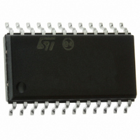
IC STEPPER MOTOR DRIVER SO-24
Manufacturer
STMicroelectronics
Type
Driverr
Datasheet
1.E-L6219R013TR.pdf
(16 pages)
Specifications of L6219R
Applications
DC Motor Driver, Stepper Motor Driver
Number Of Outputs
2/1
Current - Output
±500mA
Voltage - Load
4.5 V ~ 10 V
Voltage - Supply
4.75 V ~ 5.25 V
Operating Temperature
-20°C ~ 85°C
Mounting Type
Surface Mount
Package / Case
24-SOIC (7.5mm Width)
Product
Stepper Motor Controllers / Drivers
Operating Supply Voltage
4.5 V to 30 V
Supply Current
0.01 A
Mounting Style
SMD/SMT
Lead Free Status / RoHS Status
Lead free / RoHS Compliant
Available stocks
Company
Part Number
Manufacturer
Quantity
Price

Company:
Part Number:
L6219R013TR
Manufacturer:
SONY
Quantity:
6 219


Block diagram and pins description
Note:
6/16
Table 2.
ESD on GND, Vs, Vss, OUT 1 A and OUT 2 A is guaranteed up to 1.5 KV (human body
model, 1500 W, 100 pF).
10,16
11,15
12,14
Pin #
3,23
4,22
5,21
6,19
7,18
8,20
9,17
1,2
13
24
Sense resistor
Comparator
Vss - Logic
Reference
Vs - Load
Output A
Output B
Pin description
Ground
Ground
voltage
Input 0
Input 1
supply
supply
Phase
Name
input
RC
See pins 5,21
Connection to lower emitters of output stage for insertion of current
sense resistor
Input connected to the comparators. The voltage across the sense
resistor is feedback to this input throught the low pass filter RC CC. The
higher power transistors are disabled when the sense voltage exceeds
the reference voltage of the selected comparator. When this occurs the
current decays for a time set by RT CT (toff = 1.1 RT CT). See
Output connection. The output stage is a H bridge formed by four
transistors and four diodes suitable for switching applications
See pins 7,18
Ground connection. With pins 6 and 19 also conducts heat from die to
printed circuit copper
See input 1 (pins 9,17)
These pins and pins 8,20 (input 0) are logic inputs which select the
outputs of the comparators to set the current level. Current also depends
on the sensing resistor and reference voltage. See funcional description
This TTL-compatible logic inputs sets the direction of current flow through
the load. a high level causes current to flow from output a (source) to
output B (sink). A schmitt trigger on this input provides good noise
immunity and a delay circuit prevents output stage short circuits during
switching
A voltage applied to this pin sets the reference voltage of the
comparators, this determining the output current (also thus depending on
Rs and the two inputs input 0 and input 1)
A parallel RC network connected to this pin sets the OFF time of the
higher power transistors. The pulse generator is a monostable triggered
by the output of the comparators (toff = 1.1 RT CT)
Supply voltage input for logic circuitry
Supply voltage input for the output stages
Description
Figure 4
L6219R
Related parts for L6219R
Image
Part Number
Description
Manufacturer
Datasheet
Request
R

Part Number:
Description:
IC, MOTOR DRIVER, STEPPER, 750mA, DIP-24
Manufacturer:
STMicroelectronics
Datasheet:
Part Number:
Description:
STMicroelectronics [RIPPLE-CARRY BINARY COUNTER/DIVIDERS]
Manufacturer:
STMicroelectronics
Datasheet:
Part Number:
Description:
STMicroelectronics [LIQUID-CRYSTAL DISPLAY DRIVERS]
Manufacturer:
STMicroelectronics
Datasheet:

Part Number:
Description:
BOARD EVAL FOR MEMS SENSORS
Manufacturer:
STMicroelectronics
Datasheet:
Part Number:
Description:
NPN TRANSISTOR POWER MODULE
Manufacturer:
STMicroelectronics
Datasheet:
Part Number:
Description:
TURBOSWITCH ULTRA-FAST HIGH VOLTAGE DIODE
Manufacturer:
STMicroelectronics
Datasheet:
Part Number:
Description:
Manufacturer:
STMicroelectronics
Datasheet:
Part Number:
Description:
DIODE / SCR MODULE
Manufacturer:
STMicroelectronics
Datasheet:
Part Number:
Description:
DIODE / SCR MODULE
Manufacturer:
STMicroelectronics
Datasheet:
Part Number:
Description:
Search -----> STE16N100
Manufacturer:
STMicroelectronics
Datasheet:
Part Number:
Description:
Search ---> STE53NA50
Manufacturer:
STMicroelectronics
Datasheet:
Part Number:
Description:
NPN Transistor Power Module
Manufacturer:
STMicroelectronics
Datasheet: