L6234 STMicroelectronics, L6234 Datasheet - Page 3
L6234
Manufacturer Part Number
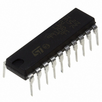
L6234
Description
IC DRIVER 3PHASE MOTOR 20-DIP
Manufacturer
STMicroelectronics
Type
Driverr
Datasheet
1.L6234.pdf
(10 pages)
Specifications of L6234
Applications
DC Motor Driver, Brushless (BLDC), 3 Phase
Number Of Outputs
1
Current - Output
2.8A
Voltage - Supply
7 V ~ 52 V
Operating Temperature
-40°C ~ 125°C
Mounting Type
Through Hole
Package / Case
20-DIP (0.300", 7.62mm)
Operating Supply Voltage
7 V to 52 V
Supply Current
0.007 A
Mounting Style
Through Hole
Motor Type
Three Phase DC Brushless
No. Of Outputs
3
Output Current
5A
Output Voltage
52V
Supply Voltage Range
7V To 42V
Driver Case Style
DIP
No. Of Pins
20
Operating Temperature Range
0°C
Rohs Compliant
Yes
Lead Free Status / RoHS Status
Lead free / RoHS Compliant
Voltage - Load
-
Lead Free Status / Rohs Status
Lead free / RoHS Compliant
Other names
497-6703-5
L6234
L6234
Available stocks
Company
Part Number
Manufacturer
Quantity
Price
Company:

Part Number:
L6234
Manufacturer:
STMicroelectronics
Quantity:
308
Part Number:
L6234D
Manufacturer:
ST
Quantity:
20 000
Company:
Part Number:
L6234LF
Manufacturer:
INF
Quantity:
3 981
Company:
Part Number:
L6234PD
Manufacturer:
STMicroelectronics
Quantity:
930
Part Number:
L6234PD
Manufacturer:
ST
Quantity:
20 000
Part Number:
L6234PD013TR
Manufacturer:
ST
Quantity:
20 000


THERMAL DATA
THERMAL CHARACTERISTICS
R
DIP16+2+2. The thermal resistance is referred to
the thermal path from the dissipating region on
the top surface of the silicon chip, to the points
along the four central pins of the package, at a
distance of 1.5 mm away from the stand-offs.
R
If a dissipating surface, thick at least 35 m, and
with a surface similar or bigger than the one
shown, is created making use of the printed cir-
cuit.
Such heatsinking surface is considered on the
bottom side of an horizontal PCB (worst case).
R
If the power dissipating pins (the four central
Figure 1: Printed Heatsink
th j-pins
th j-amb1
th j-amb2
R
R
Symbol
R
R
th j-amb1
th j-amb2
th j-case
th j-pin
Thermal Resistance, Junction to Pin
Thermal Resistance, Junction to Ambient
(see Thermal Characteristics)
Thermal Resistance, Junction to Ambient (see Thermal
Characteristics)
Thermal Resistance Junction-case
Parameter
ones), as well as the others, have a minimum
thermal connection with the external world (very
thin strips only) so that the dissipation takes place
through still air and through the PCB itself.
It is the same situation of point above, without any
heatsinking surface created on purpose on the
board.
Additional data on the PowerDip and the
PowerSO20 package can be found in:
Application Note AN467:
Thermal Characteristics of the PowerDip
20,24 Packages Soldered on 1,2,3 oz.
Copper PCB
Application Note AN668:
A New High Power IC Surface Mount Package:
PowerSO20 Power IC Packaging from Insertion
to Surface Mounting.
DIP16+2+2
12
40
50
–
PowerSO20
1.5
–
–
–
L6234
Unit
C/W
C/W
C/W
C/W
3/10
Related parts for L6234
Image
Part Number
Description
Manufacturer
Datasheet
Request
R

Part Number:
Description:
STMicroelectronics [RIPPLE-CARRY BINARY COUNTER/DIVIDERS]
Manufacturer:
STMicroelectronics
Datasheet:
Part Number:
Description:
STMicroelectronics [LIQUID-CRYSTAL DISPLAY DRIVERS]
Manufacturer:
STMicroelectronics
Datasheet:

Part Number:
Description:
BOARD EVAL FOR MEMS SENSORS
Manufacturer:
STMicroelectronics
Datasheet:
Part Number:
Description:
NPN TRANSISTOR POWER MODULE
Manufacturer:
STMicroelectronics
Datasheet:
Part Number:
Description:
TURBOSWITCH ULTRA-FAST HIGH VOLTAGE DIODE
Manufacturer:
STMicroelectronics
Datasheet:
Part Number:
Description:
Manufacturer:
STMicroelectronics
Datasheet:
Part Number:
Description:
DIODE / SCR MODULE
Manufacturer:
STMicroelectronics
Datasheet:
Part Number:
Description:
DIODE / SCR MODULE
Manufacturer:
STMicroelectronics
Datasheet:
Part Number:
Description:
Search -----> STE16N100
Manufacturer:
STMicroelectronics
Datasheet:
Part Number:
Description:
Search ---> STE53NA50
Manufacturer:
STMicroelectronics
Datasheet:
Part Number:
Description:
NPN Transistor Power Module
Manufacturer:
STMicroelectronics
Datasheet:
Part Number:
Description:
DIODE / SCR MODULE
Manufacturer:
STMicroelectronics
Datasheet: