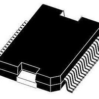
E-L6258E STMicroelectronics, E-L6258E Datasheet - Page 6

E-L6258E
Manufacturer Part Number
E-L6258E
Description
IC MOTOR DRIVER UNIV 36-PWRSOIC
Manufacturer
STMicroelectronics
Type
DMOS Dual Full Bridge Driverr
Datasheet
1.E-L6258E.pdf
(31 pages)
Specifications of E-L6258E
Applications
DC Motor Driver, Stepper Motor Driver
Number Of Outputs
2/1
Current - Output
1.2A
Voltage - Load
12 V ~ 40 V
Voltage - Supply
4.75 V ~ 5.25 V
Mounting Type
Surface Mount
Package / Case
36-PowerSOIC
Package Type
PowerSO
Operating Supply Voltage (min)
12V
Operating Supply Voltage (typ)
34V
Operating Supply Voltage (max)
40V
Current, Output, High Level
1.5 A
Temperature, Operating, Maximum
150 °C
Voltage, Input, High Level
7 V
Voltage, Input, Low Level
–0.3 V
Voltage, Supply
45 V
Operating Supply Voltage
12 V to 40 V
Mounting Style
SMD/SMT
Lead Free Status / RoHS Status
Lead free / RoHS Compliant
Operating Temperature
-
Lead Free Status / Rohs Status
Compliant
Available stocks
Company
Part Number
Manufacturer
Quantity
Price
Company:
Part Number:
E-L6258E
Manufacturer:
ROHM
Quantity:
1 950
Company:
Part Number:
E-L6258EA
Manufacturer:
NIPPON
Quantity:
2 995
Company:
Part Number:
E-L6258EXTR
Manufacturer:
ST
Quantity:
1 000
Block diagram
6/31
Figure 2.
Table 3.
Pin #
1, 36
2, 17
3
4
5
6
7
PWR_GND
PWR_GND
DISABLE
TRI_CAP
Pin connection (top view)
Pin functions
VBOOT
OUT1A
OUT2A
VCP1
VCP2
PH_1
PH_2
GND
I1_1
I0_1
I0_2
I1_2
V
VS
DD
PH_1, PH_2
PWR_GND
DISABLE
TRI_cap
OUT1A
Name
I
I
1_1
0_1
1
2
3
4
5
6
7
8
9
10
11
12
13
14
15
16
17
18
Doc ID 8688 Rev 9
Ground connection (1). They also conduct heat from die to
printed circuit copper.
These TTL compatible logic inputs set the direction of
current flow through the load. A high level causes current to
flow from OUTPUT A to OUTPUT B.
Logic input of the internal DAC (1). The output voltage of the
DAC is a percentage of the Vref voltage applied according to
the thruth
See pin 3
Bridge output connection (1)
Disables the bridges for additional safety during switching.
When not connected the bridges are enabled
Triangular wave generation circuit capacitor. The value of
this capacitor defines the output switching frequency
D96IN432E
Table 5 on page
Description
36
35
34
33
32
31
30
29
28
27
26
25
24
23
22
21
20
19
12.
PWR_GND
SENSE1
OUT1B
I3_1
I2_1
VS
EA_OUT1
EA_IN1
VREF1
SIG_GND
VREF2
EA_IN2
EA_OUT2
I2_2
I3_2
OUT2B
SENSE2
PWR_GND
L6258E


