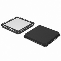
AMIS30522C5222G ON Semiconductor, AMIS30522C5222G Datasheet - Page 20

AMIS30522C5222G
Manufacturer Part Number
AMIS30522C5222G
Description
IC MOTOR DVR MICRO STEP 32QFP
Manufacturer
ON Semiconductor
Type
Stepper Motor Driverr
Datasheet
1.AMIS30522C5222RG.pdf
(29 pages)
Specifications of AMIS30522C5222G
Applications
Stepper Motor Driver, 2 Phase
Number Of Outputs
1
Current - Output
1.2A
Voltage - Supply
6 V ~ 30 V
Operating Temperature
-40°C ~ 125°C
Mounting Type
Surface Mount
Package / Case
32-VSQFP
Package
32NQFP EP
Maximum Operating Current
8 mA
Product
Stepper Motor Controllers / Drivers
Operating Supply Voltage
6 V to 30 V
Supply Current
8 mA
Mounting Style
SMD/SMT
Lead Free Status / RoHS Status
Lead free / RoHS Compliant
Voltage - Load
-
Lead Free Status / Rohs Status
Lead free / RoHS Compliant
Available stocks
Company
Part Number
Manufacturer
Quantity
Price
Company:
Part Number:
AMIS30522C5222G
Manufacturer:
ON Semiconductor
Quantity:
135
Company:
Part Number:
AMIS30522C5222G
Manufacturer:
ON Semiconductor
Quantity:
10 000
Note: t
microcontroller to shift−in the <WDEN> bit after a
power−up.
programmable through the WDT[3:0] bits. The timing is
given in Figure 16.
CLR Pin (=Hard Reset)
To reset the complete digital inside the 522, the input CLR
needs to be pulled to logic 1 during minimum time given by
t
internal registers without the need of a power−cycle, except
in sleep mode. The operation of all analog circuits is
depending on the reset state of the digital, charge pump
remains active. Logic 0 on CLR pin resumes normal
operation again. The voltage regulator remains functional
during and after the reset and the POR/WD pin is not
activated. Watchdog function is reset completely.
CLR
The duration of the watchdog timeout interval is
Logic 0 on CLR pin allows normal operation of the chip.
. (See AC Parameters) This reset function clears all
DSPI
is the time needed by the external
t
V
WDTO
DDH
VDD
VBB
t
POR/WD pin
Enable WD
Acknowledge WD
WD timer
> t
t
PU
t
WDPR
Figure 16. Watchdog Timing Diagram
POR
t
DSPI
and < t
http://onsemi.com
WDTO
20
Sleep Mode
enter a so−called “sleep mode”. This mode allows reduction
of current−consumption when the motor is not in operation.
The effect of sleep mode is as follows:
•
•
•
•
•
•
Normal operation is resumed after writing logic ‘0’ to bit
<SLP>. A start−up time is needed for the charge pump to
stabilize. After this time, NXT commands can be issued.
When the device is in sleep mode and V
than V
The bit <SLP> in SPI Control Register 2 is provided to
The drivers are put in HiZ
All analog circuits are disabled and in low−power mode
All internal registers are maintaining their logic content
NXT and DIR inputs are ignored
SPI communication remains possible (slight current
increase during SPI communication)
Oscillator and digital clocks are silent, except during
SPI communication
BB_min
t
WDRD
the device might reset.
= t
WDPR
t
POR
or = t
WDTO
t
t
t
BB
becomes lower


