AMIS30542C5421G ON Semiconductor, AMIS30542C5421G Datasheet - Page 19
AMIS30542C5421G
Manufacturer Part Number
AMIS30542C5421G
Description
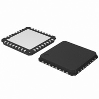
IC MOTOR DVR MICRO STEP 32QFP
Manufacturer
ON Semiconductor
Type
Micro Stepping Motor Driverr
Datasheet
1.AMIS30542C5421RG.pdf
(29 pages)
Specifications of AMIS30542C5421G
Applications
Stepper Motor Driver, 2 Phase
Number Of Outputs
1
Current - Output
2.2A
Voltage - Supply
6 V ~ 30 V
Operating Temperature
-40°C ~ 125°C
Mounting Type
Surface Mount
Package / Case
32-VSQFP
Product
Stepper Motor Controllers / Drivers
Operating Supply Voltage
6 V to 30 V
Supply Current
8 mA
Mounting Style
SMD/SMT
Lead Free Status / RoHS Status
Lead free / RoHS Compliant
Voltage - Load
-
Lead Free Status / Rohs Status
Lead free / RoHS Compliant
Available stocks
Company
Part Number
Manufacturer
Quantity
Price
Company:

Part Number:
AMIS30542C5421G
Manufacturer:
ON Semiconductor
Quantity:
10 000


Error Output
microcontroller. The signal on this output is active low and
the logic combination of:
NOT(ERRB) = <TW> OR <TSD> OR <OVCXij> OR
<OVCYij> OR <OPENi> OR <CPFAIL>
Logic Supply Regulator
with external capacitor to supply the digital part of the chip,
some low−voltage analog blocks and external circuitry. The
voltage level is derived from an internal bandgap reference.
To calculate the available drive−current for external
Watchdog Function
<WDEN> bit (Table 13: SPI CONTROL REGISTERS
(ALL SPI control registers have Read/Write Access and
default to “0” after power−on or hard reset.)). Once this bit
has been set to “1” (watchdog enable), the microcontroller
needs to re−write this bit to clear an internal timer before the
watchdog timeout interval expires. In case the timer is
activated and WDEN is acknowledged too early (before
t
of the microcontroller will occur through POR/WD pin. In
addition, a warm/cold boot bit <WD> is available (see
Tables 16 and 17) for further processing when the external
microcontroller is alive again.
CLR pin (=Hard Reset)
To reset the complete digital inside AMIS−30542, the input
CLR needs to be pulled to logic 1 during minimum time
given by t
clears all internal registers without the need of a
power−cycle, except in sleep mode. The operation of all
WDPR
This is a digital output to flag a problem to the external
AMIS−30542 has an on−chip 5 V low−drop regulator
The watchdog function is enabled/disabled through
Logic 0 on CLR pin allows normal operation of the chip.
) or not within the interval (after t
CLR
. (Table 6 AC Parameters). This reset function
V
VBB
VDD
V
POR/WD pin
DDH
DDL
Figure 16. Power−on−Reset Timing Diagram
WDTO
t
PU
), then a reset
t
POR
http://onsemi.com
19
< t
circuitry, the specified I
consumption of internal circuitry (unloaded outputs) and the
loads connected to logic outputs. See Table 5. DC
parameters
Power−On Reset (POR) Function
low” reset for external purposes. At powerup of
AMIS−30542, this pin will be kept low for some time to reset
for example an external microcontroller. A small analogue
filter avoids resetting due to spikes or noise on the V
supply.
analog circuits is depending on the reset state of the digital,
charge pump remains active. Logic 0 on CLR pin resumes
normal operation again.
the reset and the POR/WD pin is not activated. Watchdog
function is reset completely.
Sleep Mode
is provided to enter a so−called “sleep mode”. This mode
allows reduction of current−consumption when the motor is
not in operation. The effect of sleep mode is as follows:
•
•
•
•
•
•
RF
The open drain output pin POR/WD provides an “active
The voltage regulator remains functional during and after
The bit <SLP> in SPI Control Register 2 (See Table 12)
The drivers are put in HiZ
All analog circuits are disabled and in low−power mode
All internal registers are maintaining their logic content
NXT and DIR inputs are forbidden
SPI communication remains possible (slight current
increase during SPI communication)
Oscillator and digital clocks are silent, except during
SPI communication
t
PD
t
RF
load
should be reduced with the
t
t
DD
Related parts for AMIS30542C5421G
Image
Part Number
Description
Manufacturer
Datasheet
Request
R

Part Number:
Description:
ON Semiconductor [VOLTAGE REGULATOR]
Manufacturer:
ON Semiconductor
Datasheet:
Part Number:
Description:
357-036-542-201 CARDEDGE 36POS DL .156 BLK LOPRO
Manufacturer:
ON Semiconductor
Datasheet:
Part Number:
Description:
357-036-542-201 CARDEDGE 36POS DL .156 BLK LOPRO
Manufacturer:
ON Semiconductor
Datasheet:
Part Number:
Description:
357-036-542-201 CARDEDGE 36POS DL .156 BLK LOPRO
Manufacturer:
ON Semiconductor
Datasheet:
Part Number:
Description:
357-036-542-201 CARDEDGE 36POS DL .156 BLK LOPRO
Manufacturer:
ON Semiconductor
Datasheet:
Part Number:
Description:
357-036-542-201 CARDEDGE 36POS DL .156 BLK LOPRO
Manufacturer:
ON Semiconductor
Datasheet:
Part Number:
Description:
357-036-542-201 CARDEDGE 36POS DL .156 BLK LOPRO
Manufacturer:
ON Semiconductor
Datasheet:
Part Number:
Description:
357-036-542-201 CARDEDGE 36POS DL .156 BLK LOPRO
Manufacturer:
ON Semiconductor
Datasheet:
Part Number:
Description:
357-036-542-201 CARDEDGE 36POS DL .156 BLK LOPRO
Manufacturer:
ON Semiconductor
Datasheet:
Part Number:
Description:
357-036-542-201 CARDEDGE 36POS DL .156 BLK LOPRO
Manufacturer:
ON Semiconductor
Datasheet:
Part Number:
Description:
357-036-542-201 CARDEDGE 36POS DL .156 BLK LOPRO
Manufacturer:
ON Semiconductor
Datasheet:
Part Number:
Description:
Manufacturer:
ON Semiconductor
Datasheet:
Part Number:
Description:
Manufacturer:
ON Semiconductor
Datasheet:
Part Number:
Description:
Manufacturer:
ON Semiconductor
Datasheet: