AMIS30623C623BG ON Semiconductor, AMIS30623C623BG Datasheet
AMIS30623C623BG
Specifications of AMIS30623C623BG
Available stocks


Related parts for AMIS30623C623BG

AMIS30623C623BG Summary of contents
Page 1
AMIS-30623 Micro-stepping Motor Driver INTRODUCTION The AMIS−30623 is a single−chip micro−stepping motordriver with position controller and control/diagnostic interface ready to build dedicated mechatronics solutions connected remotely with a LIN master. The chip receives positioning instructions through the bus ...
Page 2
... AMIS30623C623ARG 800 mA AMIS30623C6238G 800 mA AMIS30623C6238RG 800 mA AMIS30623C623BG 800 mA AMIS30623C623BRG 800 mA *For additional information on our Pb−Free strategy and soldering details, please download the ON Semiconductor Soldering and Mounting Techniques Reference Manual, SOLDERRM/D. †For information on tape and reel specifications, including part orientation and tape sizes, please refer to our Tape and Reel Packaging Specification Brochure, BRD8011/D ...
Page 3
Table of Contents General Description . . . . . . . . . . . . . . . . . . . . . . . . . . . . Product Features . . . . . ...
Page 4
HW0 1 HW1 2 VDD 3 4 GND TST 5 LIN 6 GND 7 HW2 8 CPN 9 CPP 10 SOIC−20 Table 4. PIN DESCRIPTION Pin Name HW0 Bit 0 of LIN−ADD HW1 Bit 1 of LIN−ADD VDD Internal supply ...
Page 5
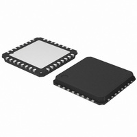
The AMIS−30623 is available in SOIC−20 and optimized NQFP−32 packages. For cooling optimizations, the NQFP has an exposed thermal pad which has to be soldered to the PCB ground plane. The ground plane needs thermal vias to conduct the head ...
Page 6
The DC parameters are guaranteed overtemperature and V currents flowing into the circuit are defined as positive. Table 5. DC PARAMETERS Symbol Pin(s) Parameter MOTORDRIVER I Max current through motor MSmax,Peak coil in normal operation I Max rms current through ...
Page 7
Table 5. DC PARAMETERS Symbol Pin(s) Parameter SUPPLY AND VOLTAGE REGULATOR V Regulated internal supply DD (Note 14) V Digital supply reset level @ ddReset V power down (Note 15 Current limitation ddLim SWITCH INPUT AND HARDWIRE ADDRESS ...
Page 8
The AC parameters are guaranteed for temperature and V The LIN transmitter and receiver physical layer parameters are compliant to LIN rev. 2.0 & 2.1. Table 6. AC PARAMETERS Symbol Pin(s) Parameter POWERUP T Power−up time pu INTERNAL OSCILLATOR f ...
Page 9
TxD LIN TH Rec(max) TH Dom(max) TH Rec(min) TH Dom(min) RxD (receiver 2) t rx_pdf Figure 5. Timing Diagram for AC Characteristics According to LIN 2.0 & 2.1 Typical Application V BAT 100 nF 100 mF ...
Page 10
Stepping Modes One of four possible stepping modes can be programmed: • Half−stepping • 1/4 micro−stepping • 1/8 micro−stepping • 1/16 micro−stepping Table 7. MAXIMUM VELOCITY SELECTION TABLE Vmax Index Vmax Hex Dec (full step/s) Group ...
Page 11
Minimum Velocity Once the maximum velocity is chosen, 16 possible values can be programmed for the minimum velocity Vmin. The table below provides the obtainable values in full−step/s. The accuracy of Vmin is derived from the internal oscillator. Table 8. ...
Page 12
Acceleration and Deceleration Sixteen possible values can be programmed for Acc (acceleration and deceleration between Vmin and Vmax). The table below provides the obtainable values in 2 full−step/s . One observes restrictions Table 9. ACCELERATION AND DECELERATION SELECTION TABLE Vmax ...
Page 13
Position Ranges A position is coded by using the binary two’s complement format. According to the positioning commands used and to the chosen stepping mode, the position range will be as shown in the following table. Table 11. POSITION RANGE ...
Page 14
The charge pump to allow driving of the H−bridges’ high side transistors. • Two pre−scale 4−bit DAC’s to set the maximum magnitude of the current through X and Y. • Two DAC’s to set the correct current ratio through ...
Page 15
Table 13. POSITION RELATED PARAMETERS Parameter Pmax – Pmin Zero Speed Hold Current Maximum Current Acceleration and Deceleration Vmin Vmax Different positioning examples are shown in the table below. Table 14. POSITIONING EXAMPLES Short motion. New positioning command in same ...
Page 16
Dual Positioning A SetDualPosition command allows the user to perform a positioning using two different velocities. The first motion is done with the specified Vmin and Vmax velocities in the SetDualPosition command, with the acceleration (deceleration) parameter already in RAM, ...
Page 17
ActPos = +30000 0 Motion direction TagPos = −30000 −10000 −20000 Figure 9. Motion Direction is Function of Difference between ActPos and TagPos R2GND 2 = R2VBAT 3 = OPEN Figure ...
Page 18
Table 15. STATE DIAGRAM OF THE HW2 COMPARATOR Previous State DriveLS Float 1 Float 1 Float 0 Float 0 Low 1 Low 1 Low 0 Low 0 High 1 High 1 High 0 High 0 The logic is controlling the ...
Page 19
Condition R2 VBAT Tsw = 1024 ms DriveLS Tsw_on = 128 ms DriveHS “R”−Comp R th HW2_Cmp State Figure 11. Timing Diagram Showing the Change in States for HW2 Comparator R2VBAT A resistor is connected between VBAT and HW2. Every ...
Page 20
R2GND 2 = R2VBAT 3 = OPEN Figure 12. Simplified Schematic Diagram of the SWI Comparator As illustrated in the drawing above, a change in state is always synchronised with DriveHS or DriveLS. ...
Page 21
DriveHS DriveLS “R”−Comp R th SWI_Cmp ESW ActPos Figure 13. Simplified Timing Diagram Showing the Change in States for SWI Comparator Main Control and Register, OTP memory + ROM Power−up Phase Power−up phase of the AMIS−30623 will not exceed 10 ...
Page 22
The circuit will return to normal mode if a valid LIN frame is received (this valid frame can be addressed to another slave). Thermal Shutdown Mode When thermal shutdown occurs, the circuit performs a <SoftStop> command and goes to motor ...
Page 23
T shutdown level T T warning level T <tw> bit T < T getstatus or getfullstatus T <tsd> bit Figure 15. Illustration of Thermal Management Situation Autarkic Functionality in Under−Voltage Condition Battery Voltage Management The AMIS−30623 monitors the battery voltage ...
Page 24
OTP Register OTP Memory Structure The table below shows how the parameters to be stored in the OTP memory are located. Table 17. OTP MEMORY STRUCTURE Address Bit 7 Bit 6 0x00 OSC3 OSC2 0x01 EnableLIN TSD2 0x02 AbsThr3 AbsThr2 ...
Page 25
DelThr[3:0] Relative threshold used for the motion detection Index DelThr DelThr Level (V) (*) ...
Page 26
Note: The Secure Position is coded on 11 bits only, providing actually the most significant bits of the position, the non coded least significant bits being set to ‘0’. The Secure Position in OTP has only 9 bits. The two ...
Page 27
Table 19. RAM REGISTERS Length (bit) Register Mnemonic Actual position ActPos Last programmed Pos/TagPos 16/11 Position Acceleration shape AccShape Coil peak current Irun Coil hold current Ihold Minimum Velocity Vmin Maximum Velocity Vmax Shaft Shaft Acceleration/ Acc deceleration Secure Position ...
Page 28
Table 20. FLAGS TABLE Length (bit) Flag Mnemonic Charge pump failure CPFail 1 Electrical defect ElDef 1 External switch ESW 1 status Electrical flag HS 1 Motion status Motion 3 Over current in coil X OVC1 1 Over current in ...
Page 29
Priority Encoder The table below describes the simplified state management performed by the main control block. Table 21. PRIORITY ENCODER State " Standby Stopped Motor Command Stopped, Motor Motion O Ihold in Coils GetActualPos LIN in-frame LIN in-frame response response ...
Page 30
Leaving <Sleep> state is equivalent to power−on−reset. 28. After power−on−reset, the <Standby> state is entered. 29. A DualPosition sequence runs with a separate set of RAM registers. The parameters that are not specified in a DualPosition command are loaded ...
Page 31
Motordriver Current Waveforms in the Coils Figure 17 below illustrates the current fed to the motor coils by the motordriver in half−step mode Coil Y Figure 17. Current Waveforms in Motor Coils X and Y in Halfstep Mode ...
Page 32
Motor Starting Phase At motion start, the currents in the coils are directly switched from <Ihold> to <Irun> with a new sine/cosine ratio corresponding to the first half (or micro−) step of the motion Charge Pump Monitoring If ...
Page 33
This can be illustrated in the following sequence given as an application example. The master can check whether there is a problem or not and decide which application strategy to adopt. Table 25. Example of Possible Sequence used to Detect ...
Page 34
Table 26. TRUTH TABLE Condition Vbemf < Average − DelThr Vbemf > Average + DelThr Vbemf < AbsThr By design, the motion will only be detected when the motor is running at the maximum velocity, not during acceleration or deceleration. ...
Page 35
FS2StallEn If <AbsThr> or <DelThr> <> 0 (i.e. motion detection is enabled), then stall detection will be activated AFTER the acceleration ramp + an additional number of full−steps, according to the following table: Table 29. ACTIVATION DELAY OF MOTION DETECTION ...
Page 36
General Description The LIN (local interconnect network serial communications protocol that efficiently supports the control of mechatronics nodes in distributed automotive applications. The physical interface implemented in the AMIS−30623 is compliant to the LIN rev. 2.0 & 2.1 ...
Page 37
With: Data error flag: (= Checksum error + StopBit error + Length error) Header error flag: (= Parity error + SynchField error) Time out flag: The message frame is not fully completed within the maximum length Bit error flag: Difference ...
Page 38
ID ID0 ID1 ID2 ID3 ID4 ID5 ID6 NOTE: <ID4> and <ID5> indicate the number of data bytes. ID5 ID4 Ndata (number of data fields Type #2: two, four or eight data ...
Page 39
Type #8: eight data bytes preparing frame with 0x3C identifier. Table 32. PREPARING FRAME #8 Bit 7 Byte Content 0 Identifier 0 1 Data 1 2 Data Data Data 4 5 Data 5 6 ...
Page 40
Dynamic ID User Defined User Defined User Defined User Defined User Defined User Defined User Defined User Defined User Defined Figure 22. Principle of Dynamic Command Assignment Commands Table Table 34. LIN COMMANDS WITH CORRESPONDING ROM POINTER Command Mnemonic GetActualPos ...
Page 41
LIN Lost Behavior Introduction When the LIN communication is broken for a duration of 25000 consecutive frames (= 1,30s @ 19200 kbit/s) AMIS−30623 sets an internal flag called “LIN lost”. The functional behavior depends on the state of OTP bits ...
Page 42
Important Remarks: 1. The Secure Position has a resolution of 11 bit. 2. Same behavior in case of HW2 float (= lost LIN address), except for entering Sleep mode. If HW2 is floating, but there is LIN communication, Sleep mode ...
Page 43
LIN Lost Before or At Power On If the LIN communication is lost before or at power on, the <ActPos> register does not reflect the “real” actual position LIN – lost a referencing is started using DualPositioning. A ...
Page 44
Introduction The LIN Master will have to use commands to manage the different application tasks the AMIS−30623 can feature. The commands summary is given in Table 37 below. Table 37. COMMANDS SUMMARY Command Mnemonic Code READING COMMAND 0x00 GetActualPos 0x01 ...
Page 45
Some frames implement a <Broad> bit that allows addressing a command to all the AMIS−30623 circuits connected to the same LIN bus. <Broad> is active when at ‘0’, in which case the physical address provided in the frame is thus ...
Page 46
Table 40. GetActualPos PREPARING FRAME TYPE #6 Bit 7 Byte Content 0 Identifier 0 1 Data 1 ESW 2 Data 2 3 Data 3 4 Data 4 VddReset 5 Data 5 6 Data 6 7 Data 7 8 Data 8 ...
Page 47
GetFullStatus This command is provided to the circuit by the LIN master to get a complete status of the circuit and the stepper−motor. Refer to RAM Registers and Flags Table to see the meaning of the parameters sent to the ...
Page 48
The master sends a type #8 preparing frame. After the type#8 preparing frame, the master sends a reading frame type#6 to retrieve the circuit’s in−frame response. Table 46. GetFullStatus PREPARING FRAME TYPE#8 Bit 7 Byte Content 0 Identifier 0 ...
Page 49
GetOTPparam This command is provided to the circuit by the LIN master after a preparing frame (see Preparing frames), to read the GetOTPparam corresponds to a LIN in−frame response with 0x3D indirect ID. 1. The master sends a type #7 ...
Page 50
Table 52. GetOTPparam READING FRAME TYPE #6 Bit 7 Byte Content 0 Identifier 0 1 Data 1 2 Data 2 3 Data 3 4 Data 4 5 Data 5 6 Data 6 7 Data 7 8 Data 8 9 Checksum ...
Page 51
GotoSecurePosition corresponds to the following LIN writing frame (type #1). Table 54. GotoSecurePosition WRITING FRAME TYPE #1 Bit 7 Byte Content 0 Identifier * 1 Data 1 2 Data Broad 3 Checksum Where: (*) according to parity computation Broad: If ...
Page 52
RunVelocity This command is provided to the circuit by the LIN Master in order to put the motor in continuous motion state. Note: in this mode (RunVelocity), the shaft bit has no impact on the direction of movement. RunVelocity corresponds ...
Page 53
SetStallParam This command sets the motion detection parameters and the related stepper−motor parameters, such as the minimum and maximum velocity, the run and hold current, SetStallParam corresponds to a 0x3C LIN command (type #4). Table 59. SetStallParam WRITING FRAME TYPE ...
Page 54
SetOTPparam This command is provided to the circuit by the LIN master to program the content D[7:0] of the OTP memory byte OTPA[2:0] and to zap it. SetMotorParam corresponds to a 0x3C LIN writing frames (type #4). Table 61. SetOTPparam ...
Page 55
Four (4) Data bytes frame with general purpose identifier (type #1). Note: The dynamic ID allocation has to be assigned to ‘General Purpose 4 Data bytes’ ROM pointer, i.e. ‘0001’. Table 63. SetPosition WRITING FRAME TYPE #1 Bit 7 ...
Page 56
SetPositionShort This command is provided to the circuit by the LIN Master to drive one, two or four motors to a given absolute position. It applies only for half stepping mode (StepMode[1:0] = “00”) and is ignored when in other ...
Page 57
Eight (8) data bytes frame for four (4) motors, with specific identifier (type #2) Table 67. SetPositionShort WRITING FRAME TYPE #2 Bit 7 Byte Content 0 Identifier * 1 Data 1 2 Data 2 3 Data 3 4 Data ...
Page 58
Table 69. SLEEP WRITING FRAME Bit 7 Byte Content 0 Identifier 0 1 Data 1 2 Data 2 3 Checksum SoftStop If a SoftStop command occurs during a motion of the stepper motor, it provokes an immediate deceleration to Vmin ...
Page 59
PACKAGE DIMENSIONS SOIC 20 W CASE 751AQ−01 ISSUE O http://onsemi.com 59 ...
Page 60
PACKAGE DIMENSIONS NQFP−32, 7x7 CASE 560AA−01 ISSUE O http://onsemi.com 60 ...
Page 61
... Opportunity/Affirmative Action Employer. This literature is subject to all applicable copyright laws and is not for resale in any manner. PUBLICATION ORDERING INFORMATION LITERATURE FULFILLMENT: Literature Distribution Center for ON Semiconductor P.O. Box 5163, Denver, Colorado 80217 USA Phone: 303−675−2175 or 800−344−3860 Toll Free USA/Canada Fax: 303− ...