MC3479P ON Semiconductor, MC3479P Datasheet
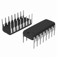
IC DRIVER STEPPER MOTOR 16DIP

MC3479P

Manufacturer Part Number
MC3479P
Description
IC DRIVER STEPPER MOTOR 16DIP
Manufacturer
ON Semiconductor
Type
Stepper Motor Controllerr
Datasheet

Specifications of MC3479P

Applications
Stepper Motor Driver, 2 Phase
Number Of Outputs
1
Current - Output
350mA
Voltage - Supply
7.2 V ~ 16.5 V
Operating Temperature
0°C ~ 70°C
Mounting Type
Through Hole
Package / Case
16-DIP (0.300", 7.62mm)
Product
Stepper Motor Controllers / Drivers
Supply Current
75 mA
Mounting Style
Through Hole
Lead Free Status / RoHS Status
Contains lead / RoHS non-compliant
Voltage - Load
-
Lead Free Status / Rohs Status
Lead free / RoHS Compliant
Other names
MC3479POS

Available stocks

Company
Part Number
Manufacturer
Quantity
Price
Part Number:
MC3479P
Manufacturer:
MOTOROLA
Quantity:
5
Part Number:
MC3479P
Manufacturer:
ON/安森美
Quantity:
20 000
Part Number:
MC3479PG
Manufacturer:
Tusonix
Quantity:
21 000
Part Number:
MC3479PG
Quantity:
2 395
Company:
Part Number:
MC3479PG
Quantity:
60 000
MC3479
Stepper Motor Driver
bipolar mode. The circuit consists of four input sections, a logic
decoding/sequencing section, two driver−stages for the motor coils,
and an output to indicate the Phase A drive state.
Features
*For additional information on our Pb−Free strategy and soldering details, please
CW/CCW
Full/Half
Step
© Semiconductor Components Industries, LLC, 2006
June, 2006 − Rev. 7
ORDERING INFORMATION
download the ON Semiconductor Soldering and Mounting Techniques
Reference Manual, SOLDERRM/D.
The MC3479 is designed to drive a two−phase stepper motor in the
Single Supply Operation: 7.2 to 16.5 V
350 mA/Coil Drive Capability
Clamp Diodes Provided for Back−EMF Suppression
Selectable CW/CCW and Full/Half Step Operation
Selectable High/Low Output Impedance (Half Step Mode)
TTL/CMOS Compatible Inputs
Input Hysteresis: 400 mV Minimum
Phase Logic Can Be Initialized to Phase A
Phase A Output Drive State Indication (Open−Collector)
Pb−Free Package is Available*
MC3479P
MC3479PG
OIC
Clk
Device
F/H Step
CW/CCW
Clock
OIC
Figure 1. Representative Block Diagram
Temperature Range
T
A
Operating
= 0° to +70°C
Phase A
Logic
V
M
(Pb−Free)
Bias/Set
Package
PDIP−16
PDIP−16
Driver
Driver
GND
25 Units / Rail
Shipping
1
L1
L2
V
L3
L4
D
CW/CCW
Full/Half Step
OIC
Clk
Bias/Set
GND
A
WL
YY
WW
G
16
1
OIC
Clk
V
INPUT TRUTH TABLE
L2
L1
MARKING DIAGRAM
D
PIN CONNECTIONS
http://onsemi.com
1
2
3
4
5
6
7
8
= Assembly Location
= Wafer Lot
= Year
= Work Week
= Pb−Free Package
AWLYYWWG
MC3479P
(Top View)
Input Low
Full Step
Positive Edge Triggered
Publication Order Number:
Hi Z
CW
CASE 648C
P SUFFIX
PDIP−16
16
15
14
13
12
10
11
9
V
L3
L4
Phase A
CW/CCW
Full/Half
Step
M
Input High
GND
Half Step
MC3479/D
Low Z
CCW

Related parts for MC3479P

MC3479P Summary of contents

Page 1

... Semiconductor Components Industries, LLC, 2006 June, 2006 − Rev Driver Driver L4 Bias/Set GND Package Shipping PDIP−16 25 Units / Rail PDIP−16 (Pb−Free) 1 http://onsemi.com PDIP−16 P SUFFIX CASE 648C MARKING DIAGRAM 16 MC3479P AWLYYWWG Assembly Location WL = Wafer Lot YY = Year WW = Work Week G = Pb−Free Package PIN CONNECTIONS ...

Page 2

MAXIMUM RATINGS Rating Supply Voltage Clamp Diode Cathode Voltage (Pin 1) Driver Output Voltage Drive Output Current/Coil Input Voltage (Logic Controls) Bias/Set Current Phase A Output Voltage Phase A Sink Current Junction Temperature Storage Temperature Range Stresses exceeding Maximum Ratings ...

Page 3

DC ELECTRICAL CHARACTERISTICS (Notes 2, 3) unless otherwise noted.) Characteristic PHASE A OUTPUT Output Low Voltage Off State Leakage Current POWER SUPPLY Power Supply Current ( OHD ( OHD ( ...

Page 4

... V 0 Bias/Set MC3479P L4 14 Clk 7 OIC CCW 4.0 k Figure 2. AC Test Circuit PIN FUNCTION DESCRIPTION Pin # Function Symbol 16 Power Supply Ground GND 12 Clamp Diode Voltage Driver Outputs L1, L2 L3, 14 Bias/Set B/S 7 Clock Clk 9 Full/Half Step F/HS 10 Clockwise/ CW/CCW Counterclockwise 8 Output Impedance ...

Page 5

General The MC3479 integrated circuit is designed to drive a stepper positioning motor in applications such as disk drives and robotics. The outputs can provide up to 350 mA to each of two coils of a two−phase motor. The outputs ...

Page 6

V D This pin allows for provision of a current path for the motor coil current during switching, in order to suppress back−EMF voltage spikes normally connected (Pin 16) through a diode (zener or regular), ...

Page 7

Clk Bias/Set CW/CCW Phase Phase A Output Phase A Output The value of R (between this pin and ground) ...

Page 8

100 150 200 250 I (mA) BS Figure 8. Power Supply Current For example, assume an application where V motor requires 200 mA/coil, operating at room temperature ...

Page 9

Typ Phase A Clock Digital Inputs CW/CCW Full/Half Step OIC Set Normal Operation Figure 12. Typical Applications Circuit Normal Operation Reduced Power − Suggested value for R − R calculation (see text) must take into account B ...

Page 10

... Opportunity/Affirmative Action Employer. This literature is subject to all applicable copyright laws and is not for resale in any manner. PUBLICATION ORDERING INFORMATION LITERATURE FULFILLMENT: Literature Distribution Center for ON Semiconductor P.O. Box 5163, Denver, Colorado 80217 USA Phone: 303−675−2175 or 800−344−3860 Toll Free USA/Canada Fax: 303− ...

Related keywords