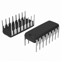
MC3479PG ON Semiconductor, MC3479PG Datasheet - Page 5

MC3479PG
Manufacturer Part Number
MC3479PG
Description
IC DRIVER STEPPER MOTOR 16DIP
Manufacturer
ON Semiconductor
Type
Stepper Motor Controllerr
Datasheet
1.MC3479P.pdf
(10 pages)
Specifications of MC3479PG
Applications
Stepper Motor Driver, 2 Phase
Number Of Outputs
1
Current - Output
350mA
Voltage - Supply
7.2 V ~ 16.5 V
Operating Temperature
0°C ~ 70°C
Mounting Type
Through Hole
Package / Case
16-DIP (0.300", 7.62mm)
Product
Stepper Motor Controllers / Drivers
Supply Current
75 mA
Mounting Style
Through Hole
Lead Free Status / RoHS Status
Lead free / RoHS Compliant
Voltage - Load
-
Lead Free Status / Rohs Status
Lead free / RoHS Compliant
Other names
MC3479PGOS
Available stocks
Company
Part Number
Manufacturer
Quantity
Price
Company:
Part Number:
MC3479PG
Manufacturer:
Tusonix
Quantity:
21 000
General
stepper positioning motor in applications such as disk drives
and robotics. The outputs can provide up to 350 mA to each
of two coils of a two−phase motor. The outputs change state
with each low−to−high transition of the clock input, with the
new output state depending on the previous state, as well as
the input conditions at the logic controls.
function of the resistor connected between Pin 6 and ground
(see section on Bias/Set operation). Whenever the outputs
The MC3479 integrated circuit is designed to drive a
The maximum sink current available at the outputs is a
F/HS,
CW/CCW
Inputs
Clk
Phase A
Output
B/S
L1 − L4
Outputs
R
3.0 V
B
0
0
3.0 V
I
BS
t
PCD
1.5 V
PW
CLKH
6.0 V
Transistors
To L3, L4
I′
BS
Current
Drivers
Figure 4. Clock Timing (Refer to Figure 2)
Logic
and
APPLICATION INFORMATION
1.5 V
PW
Figure 5. Output Stages
CLKL
http://onsemi.com
t
su
1.5 V
CW / CCW
V
MC3479
M
t
h
5
t
PHLA
F/HS
Outputs
Figure 5), which when connected to a two−phase motor,
provide two full−bridge configurations (L3 and L4 are not
shown in Figure 5). The polarities applied to the motor coils
depend on which transistor (Q
which in turn depends on the inputs and the decoding
circuitry.
are to be in a high impedance state, both transistors (Q
Q
Q
Q
L
H
L
The outputs (L1−L4) are high current outputs (see
Logic Decoding
of Figure 5) of each output are off.
Inputs
Circuit
L1
t
PLHA
Motor Coil
Clk
OIC
Parasitic
Diodes
V
D
L2
Note: t
input signals are p 10 ns.
H
or Q
r
, t
f
(10% to 90%) for
Q
Q
L
H
L
) of each output is on,
H
and


