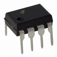
FAN6961DY Fairchild Semiconductor, FAN6961DY Datasheet - Page 3

FAN6961DY
Manufacturer Part Number
FAN6961DY
Description
IC PFC CONTROLLER DCM 8DIP
Manufacturer
Fairchild Semiconductor
Datasheet
1.FAN6961SZ.pdf
(13 pages)
Specifications of FAN6961DY
Mode
Discontinuous Conduction (DCM)
Frequency - Switching
60kHz
Current - Startup
10µA
Voltage - Supply
13.5 V ~ 24.5 V
Operating Temperature
-40°C ~ 125°C
Mounting Type
Through Hole
Package / Case
8-DIP (0.300", 7.62mm)
Lead Free Status / RoHS Status
Lead free / RoHS Compliant
© 2009 Fairchild Semiconductor Corporation
FAN6961 • Rev. 1.0.3
Marking Information
Pin Configuration
Pin Definitions
Pin #
1
2
3
4
5
6
7
8
Name
COMP
GATE
MOT
GND
ZCD
VCC
INV
CS
FAN6961
TPM
Description
Inverting Input of the Error Amplifier. INV is connected to the converter output via a resistive
divider. This pin is also used for over-voltage clamping and open-loop feedback protection.
Output of the Error Amplifier. To create a precise clamping protection, a compensation
network between this pin and GND is suggested.
Maximum On Time. A resistor from MOT to GND is used to determine the maximum on-time of
the external power MOSFET. The maximum output power of the converter is a function of the
maximum on time.
Current Sense. Input to the over-current protection comparator. When the sensed voltage
across the sense resistor reaches the internal threshold (0.8V), the switch is turned off to
activate cycle-by-cycle current limiting.
Zero Current Detection. This pin is connected to an auxiliary winding via a resistor to detect
the zero crossing of the switch current. When the zero crossing is detected, a new switching
cycle is started. If it is connected to GND, the device is disabled.
Ground. The power ground and signal ground. Placing a 0.1µF decoupling capacitor between
VCC and GND is recommended.
Driver Output. Totem-pole driver output to drive the external power MOSFET. The clamped
gate output voltage is 16.5V.
Power Supply. Driver and control circuit supply voltage.
Figure 4.
Figure 3. Marking Information
VCC
INV
DIP and SOP Pin Configuration (Top View)
8
1
F- Fairchild Logo
Z- Plant Code
X- Year Code
Y- Week Code
TT: Die Run Code
T: Package Type (S=SOP, D=DIP)
P: Z: Pb Free
M: Manufacture Flow Code
GATE
COMP
7
2
3
GND
MOT
6
3
ZCD
CS
5
4
Y: Green Compound
www.fairchildsemi.com


