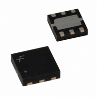
FPF2146 Fairchild Semiconductor, FPF2146 Datasheet - Page 11

FPF2146
Manufacturer Part Number
FPF2146
Description
IC LOAD SWITCH REV CURR BK 6-MLP
Manufacturer
Fairchild Semiconductor
Type
High Side Switchr
Datasheet
1.FPF2146.pdf
(13 pages)
Specifications of FPF2146
Number Of Outputs
1
Rds (on)
160 mOhm
Internal Switch(s)
Yes
Current Limit
400mA
Voltage - Input
1.8 ~ 5.5 V
Operating Temperature
-40°C ~ 85°C
Mounting Type
Surface Mount
Package / Case
6-MLP
Input Voltage
1.8 to 5.5V
Power Switch On Resistance
120mOhm
Output Current
400mA
Mounting
Surface Mount
Package Type
MLP EP
Operating Temperature (min)
-40C
Operating Temperature (max)
85C
Operating Temperature Classification
Industrial
Pin Count
6
Power Dissipation
1.2W
Lead Free Status / RoHS Status
Lead free / RoHS Compliant
Other names
FPF2146TR
FPF2140/42/43/44/46/47 Rev. D
Application Notes
Power Good
FPF214X family has a "Power Good" feature. PGOOD pin is an
open-drain MOSFET which asserts high when the output
voltage reaches 90% of the input voltage.
PGOOD pin requires an external pull up resistor that is
connected to the output voltage when there is no battery in the
load side and the logic level of the subsequent controller
permits. This would give logic levels similar to a CMOS output
stage for PGOOD, while still keeping the option to tie the pull-up
to a different supply voltage. A typical value of 100KΩ is
recommended to be used as pull up resistor. The PGOOD pin
status is independent of the ON pin position. This mean that
PGOOD pin stays low when the load switch is OFF. If the Power
Good feature is not used in the application the pin can be
connected directly to GND.
V
V
IN1
IN2
Power good function in sequential startup. No battery is loaded to the output
TP
OFF ON
100KΩ
100KΩ
Startup Power Sequence
ON
V
ON
PGOOD
V
PGOOD
IN1
IN2
FPF2140/2/
FPF2140/2/
11
3/4/6/7
3/4/6/7
GND
GND
Sequential Startup using Power Good
The power good pin can be connected to another load switch's
enable pin to implement sequential startup. PGOOD pin asserts
low when the load switch is OFF. This feature allows driving a
subsequent circuit. The above diagram illustrates power good
function in sequential startup. As the V
switch starts to ramp to the 90% of its input voltage the second
switch remains in OFF state. Whereas the V
90% threshold, power good signal becomes active and asserts
high. This signal will turn on the second load switch and V
will start to increase. The total startup time may vary according
to the difference between supply voltages that are used in the
application.
FLAGB
FLAGB
V
V
OUT1
OUT2
OUT1
To Load
OUT1
To Load
of the first load
www.fairchildsemi.com
passes the
OUT2


