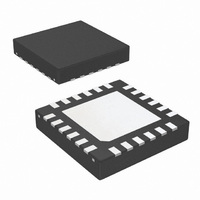
LM26480SQ-AA/NOPB National Semiconductor, LM26480SQ-AA/NOPB Datasheet - Page 21

LM26480SQ-AA/NOPB
Manufacturer Part Number
LM26480SQ-AA/NOPB
Description
IC REG BUCK/LDO DUAL 1.5A 24LLP
Manufacturer
National Semiconductor
Specifications of LM26480SQ-AA/NOPB
Applications
Processor
Voltage - Supply
2.8 V ~ 5.5 V
Operating Temperature
-40°C ~ 85°C
Mounting Type
Surface Mount
Package / Case
24-LLP
Operating Temperature (max)
85C
Operating Temperature (min)
-40C
Pin Count
24
Mounting
Surface Mount
Package Type
LLP EP
Case Length
4mm
Screening Level
Industrial
For Use With
LM26480SQ-AAEV - BOARD EVALUATION LM26480SQ-AA
Lead Free Status / RoHS Status
Lead free / RoHS Compliant
Current - Supply
-
Lead Free Status / Rohs Status
Compliant
Other names
LM26480SQ-AATR
Available stocks
Company
Part Number
Manufacturer
Quantity
Price
Company:
Part Number:
LM26480SQ-AA/NOPB
Manufacturer:
TI
Quantity:
3 400
Part Number:
LM26480SQ-AA/NOPB
Manufacturer:
NS/国半
Quantity:
20 000
Vout (V)
Target
Application Notes
EXTERNAL COMPONENT SELECTION
The output voltages of the bucks of the LM26480 are estab-
lished by the feedback resistor dividers R1 and R2 shown on
the application circuit above. The equation for determining V
is: V
Buck FBx pin.
The Buck control loop will force the voltage on V
V ±3%.
The above table shows ideal resistor values to establish buck
voltages from 0.8V to 3.3 V along with common resistor val-
L
0.8
0.9
1.1
1.2
1.3
1.4
1.5
1.6
1.7
1.8
1.9
2.1
2.2
2.3
2.4
2.5
2.6
2.7
2.8
2.9
3.1
3.2
3.3
SW
1
2
3
OUT
1,2
= V
Inductor
R1 (KΩ)
Ideal Resistor Values
FB
120
160
200
240
280
320
360
400
440
427
463
498
450
480
422
446
471
400
420
440
460
480
500
520
540
560
(R1+R2)/R2 where V
R2 (KΩ)
200
200
200
200
200
200
200
200
200
178
178
178
150
150
124
124
124
100
100
100
100
100
100
100
100
100
Value
R1 (KΩ)
2.2
FB
Common R Values
121
162
200
240
280
324
357
402
442
432
464
499
453
475
422
442
475
402
422
442
464
475
499
523
536
562
is the voltage on the
R2 (KΩ)
FB
to be 0.50
200
200
200
200
200
200
200
200
200
178
178
178
150
150
124
124
124
100
100
100
100
100
100
100
100
100
Unit
µH
W/ Com/R (V)
Actual VOUT
21
0.803
0.905
1.393
1.505
1.605
1.713
1.803
1.902
2.083
2.202
2.282
2.415
2.875
2.995
3.115
1.31
2.01
2.51
2.61
2.71
2.82
3.18
3.31
1.1
1.2
SW1,2 inductor
1
ues to establish these voltages. Common resistors do not
always produce the target value, error is given in the delta
column.
In addition to the resistor feedback, capacitor feedback C1 is
always required, and depending on the output voltage capac-
itor C2 is also required. See the application diagram below
and the above table for these requirements.
Description
Actual VOUT
Delta from
Target (V)
-0.008
-0.017
-0.018
-0.025
-0.005
0.002
0.005
0.005
0.005
0.013
0.003
0.002
0.002
0.015
0.015
-0.02
0.01
0.01
0.01
0.01
0.01
0.02
0.01
0
0
0
D.C.R. 70 mΩ
Feedback Capacitors
C1(pF)
8.2
8.2
8.2
8.2
8.2
8.2
8.2
8.2
8.2
8.2
8.2
8.2
8.2
8.2
6.8
6.8
6.8
6.8
15
15
15
15
12
12
10
10
30040410
Notes
C2(pF)
none
none
none
none
none
none
none
none
none
none
none
none
none
none
none
none
none
none
none
33
33
33
33
33
33
33
www.national.com
Buck1
Buck1
Buck2
Buck2
Only
Only
And
>
^
^
|
|
|
|
|
|
|
|
|
|
|
|
|
|
|
|


