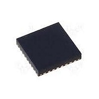
MAX17020ETJ+ Maxim Integrated Products, MAX17020ETJ+ Datasheet - Page 24

MAX17020ETJ+
Manufacturer Part Number
MAX17020ETJ+
Description
IC CTLR PWM DUAL STEP DN 32-TQFN
Manufacturer
Maxim Integrated Products
Series
Quick-PWM™r
Type
Dual Quick-PWM Step-Down Controllerr
Datasheet
1.MAX17020ETJT.pdf
(34 pages)
Specifications of MAX17020ETJ+
Applications
Power Supplies
Current - Supply
1mA
Voltage - Supply
6 V ~ 24 V
Operating Temperature
-40°C ~ 85°C
Mounting Type
Surface Mount
Package / Case
32-TQFN Exposed Pad
Output Voltage Range
0.7 V to 5.5 V
Input Voltage Range
6 V to 24 V
Input Current
1 mA
Power Dissipation
2.76 W
Operating Temperature Range
- 40 C to + 85 C
Mounting Style
SMD/SMT
Lead Free Status / RoHS Status
Lead free / RoHS Compliant
When V
edge), the controller stops switching, and DH and DL are
pulled low and a 10Ω switch discharges the outputs.
When the 2V POR falling-edge threshold is reached, the
DL state no longer matters since there is not enough volt-
age to force the switching MOSFETs into a low on-resis-
tance state, so the controller pulls DL high, allowing a
soft discharge of the output capacitors (damped
response). However, if the V
the falling POR threshold, DL remains low until the error
comparator has been properly powered up and triggers
an on-time. Only one enable input needs to be toggled
to clear the fault latches and activate both outputs.
The MAX17020 includes voltage soft-start and soft-
shutdown—slowly ramping up and down the target volt-
age. During startup, the slew-rate control softly slews
the preset/fixed target voltage over a 1ms startup peri-
od or its tracking voltage (REFIN2 < 2V) with a 1mV/μs
slew rate. This long startup period reduces the inrush
current during startup.
When ON1 or ON2 is pulled low or the output undervolt-
age fault latch is set, the respective output automatically
enters soft-shutdown—the regulator enters PWM mode
and ramps down its preset/fixed output voltage over a
1ms period or its tracking voltage (REFIN2 < 2V) with a
1mV/μs slew rate. After the output voltage drops below
0.1V, the MAX17020 pulls DL high, clamping the output
and LX switching node to ground, preventing leakage
currents from pulling up the output and minimizing the
negative output voltage undershoot during shutdown.
DC output-accuracy specifications in the Electrical
Characteristics table refer to the error comparator’s
threshold. When the inductor continuously conducts, the
MAX17020 regulates the valley of the output ripple, so
the actual DC output voltage is lower than the slope-com-
pensated trip level by 50% of the output ripple voltage.
For PWM operation (continuous conduction), the output
voltage is accurately defined by the following equation:
where V
the integrator’s gain, and V
voltage (V
the Output Capacitor Selection section).
In discontinuous conduction (I
longer off-times allow the slope compensation to
increase the threshold voltage by as much as 1%, so
Dual Quick-PWM Step-Down Controller
with Low-Power LDO, RTC Regulator
24
______________________________________________________________________________________
CC
NOM
RIPPLE
drops below the UVLO threshold (falling
V
OUT PWM
is the nominal feedback voltage, A
= ESR x ΔI
(
Soft-Start and Soft-Shutdown
)
=
V
NOM
CC
RIPPLE
INDUCTOR
recovers before reaching
OUT
+
⎛
⎜
⎝
V
2
RIPPLE
is the output ripple
Output Voltage
A
< I
CCV
, as described in
LOAD(SKIP)
⎞
⎟
⎠
CCV
), the
is
the output voltage regulates slightly higher than it would
in PWM operation.
The internal integrator improves the output accuracy by
removing any output accuracy errors caused by the
slope compensation, output ripple voltage, and error-
amplifier offset. Therefore, the DC accuracy (in forced-
PWM mode) depends on the integrator’s gain, the inte-
grator’s offset, and the accuracy of the integrator’s refe-
rence input.
Connect FB1 to GND for fixed 5V operation. Connect
FB1 to V
external resistive voltage-divider from OUT1 to analog
ground to adjust the output voltage between 0.7V and
5.5V. During soft-shutdown, application circuits config-
ured for adjustable feedback briefly switch modes when
FB1 drops below the 110mV dual-mode threshold.
Choose R
approximately 49.9kΩ and solve for R
from OUT1 to FB1) using the following equation:
Connect REFIN2 to V
Connect REFIN2 to RTC (3.3V) for fixed 1.05V operation.
Connect REFIN2 to an external resistive voltage-divider
from REF to analog ground to adjust the output voltage
between 0V and 2V.
Choose R
be approximately 49.9kΩ and solve for R
tance from REF to REFIN2) using the equation:
PGOOD is the open-drain output that continuously
monitors the output voltage for undervoltage and over-
voltage conditions. PGOOD_ is actively held low in shut-
down (ON_ = GND), during soft-start or soft-shutdown.
Approximately 20μs (typ) after the soft-start
terminates, PGOOD_ becomes high impedance as long
as the feedback voltage exceeds 85% of the nominal
fixed-regulation voltage or within 150mV of the REFIN2
input voltage. PGOOD_ goes low if the feedback volt-
age drops 16% below the fixed target voltage, or if the
output voltage drops 150mV below the dynamic REFIN2
voltage, or if the SMPS controller is shut down. For a
CC
REFINL
FBL
R
for fixed 1.5V operation. Connect FB1 to an
REFINH
R
(resistance from FB1 to AGND) to be
FBH
Power-Good Outputs (PGOOD)
(resistance from REFIN2 to GND) to
Adjustable/Fixed Output Voltages
=
=
R
R
FBL
CC
REFINL
×
for fixed 3.3V operation.
and Fault Protection
⎛
⎝ ⎜
V
×
0 7
OUT
⎛
⎝ ⎜
.
V
V
V
OUT
1
REF
Internal Integrator
−
1
2
FBH
⎞
⎠ ⎟
−
REFINH
1
⎞
⎠ ⎟
(resistance
(resis-


