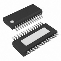
MAX8734AEEI+ Maxim Integrated Products, MAX8734AEEI+ Datasheet - Page 21

MAX8734AEEI+
Manufacturer Part Number
MAX8734AEEI+
Description
IC PWR SUPPLY CONTROLLER 28QSOP
Manufacturer
Maxim Integrated Products
Datasheet
1.MAX8734AEEIT.pdf
(33 pages)
Specifications of MAX8734AEEI+
Applications
Power Supply Controller
Voltage - Input
4.5 ~ 24 V
Current - Supply
25µA
Operating Temperature
-40°C ~ 85°C
Mounting Type
Surface Mount
Package / Case
28-QSOP
Product
Power Monitors
Operating Temperature Range
- 40 C to + 85 C
Mounting Style
SMD/SMT
Accuracy
1.5 %
Supply Current (max)
50 uA
Supply Voltage (max)
4.5 V
Supply Voltage (min)
24 V
Case
SSOP
Dc
06+
Lead Free Status / RoHS Status
Lead free / RoHS Compliant
Voltage - Supply
-
Lead Free Status / Rohs Status
Lead free / RoHS Compliant
undervoltage-protection circuit, this current-limit
method is effective in almost every circumstance.
A negative current limit prevents excessive reverse
inductor currents when V
tive current-limit threshold is set to approximately 120%
of the positive current limit and therefore tracks the
positive current limit when ILIM_ is adjusted.
The current-limit threshold is adjusted with an external
voltage-divider at ILIM_. The current-limit threshold
adjustment range is from 50mV to 300mV. In the
adjustable mode, the current-limit threshold voltage is
precisely 1/10th the voltage at ILIM_. The threshold
defaults to 100mV when ILIM_ is connected to V
Figure 8. Current Sensing Using Sense Resistor
(MAX8732A/MAX8733A)
Figure 9. More Accurate Current Sensing with Adjusted
Schottky Connection
Supply Controllers for Notebook Computers
High-Efficiency, Quad-Output, Main Power-
MAX8732A
MAX8733A
MAX8732A
MAX8733A
______________________________________________________________________________________
DH_
CS_
DH_
CS_
LX_
DL_
DL_
LX_
OUT
sinks current. The nega-
V+
V+
OUT_
OUT_
CC
.
The logic threshold for switchover to the 100mV default
value is approximately V
Carefully observe the PC board layout guidelines to
ensure that noise and DC errors do not corrupt the cur-
rent-sense signals at CS_. Mount or place the device
close to the synchronous rectifier or sense resistor
(whichever is used) with short, direct traces, making a
Kelvin-sense connection to the sense resistor. The cur-
rent-sense accuracy of Figure 8 is degraded if the
Schottky diode conducts during the synchronous recti-
fier on-time. To ensure that all current passes through
the sense resistor, connect the Schottky diode in paral-
lel with only the synchronous rectifier (Figure 9) if the
voltage drop across the synchronous rectifier and
sense resistor exceeds the Schottky diode’s forward
voltage. Note that at high temperatures, the on-resis-
tance of the synchronous rectifier increases and the
forward voltage of the Schottky diode decreases.
The DH_ and DL_ gate drivers sink 2.0A and 3.3A,
respectively, of gate drive, ensuring robust gate drive for
high-current applications. The DH_ floating high-side
MOSFET drivers are powered by diode-capacitor charge
pumps at BST_. The DL_ synchronous-rectifier drivers are
powered by LDO5.
The internal pulldown transistors that drive DL_ low
have a 0.6Ω typical on-resistance. These low on-resis-
tance pulldown transistors prevent DL_ from being
pulled up during the fast rise time of the inductor nodes
due to capacitive coupling from the drain to the gate of
the low-side synchronous-rectifier MOSFETs. However,
for high-current applications, some combinations of
high- and low-side MOSFETS may cause excessive
gate-drain coupling, which leads to poor efficiency and
EMI-producing shoot-through currents. Adding a resis-
tor in series with BST_ increases the turn-on time of the
Figure 10. Reducing the Switching-Node Rise Time
MAX8732A
MAX8733A
MAX8734A
MOSFET Gate Drivers (DH_, DL_)
BST
DH
LX
CC
10Ω
- 1V.
5V
V
IN
21


