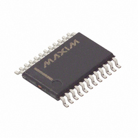
DS1780E Maxim Integrated Products, DS1780E Datasheet - Page 11

DS1780E
Manufacturer Part Number
DS1780E
Description
IC CPU PERIPHERAL MON 24-TSSOP
Manufacturer
Maxim Integrated Products
Datasheet
1.DS1780E.pdf
(28 pages)
Specifications of DS1780E
Function
Thermal Monitor, CPU Peripherals
Topology
ADC (Sigma Delta), Comparator, Fan Speed Control, Register Bank
Sensor Type
Internal
Sensing Temperature
-40°C ~ 125°C
Output Type
I²C™/SMBus™
Output Alarm
No
Output Fan
Yes
Voltage - Supply
2.8 V ~ 5.75 V
Operating Temperature
-40°C ~ 125°C
Mounting Type
Surface Mount
Package / Case
24-TSSOP
Full Temp Accuracy
+/- 12 %
Digital Output - Bus Interface
Serial (2-Wire)
Digital Output - Number Of Bits
8 bit
Maximum Operating Temperature
+ 125 C
Minimum Operating Temperature
- 40 C
Lead Free Status / RoHS Status
Contains lead / RoHS non-compliant
Available stocks
Company
Part Number
Manufacturer
Quantity
Price
Company:
Part Number:
DS1780E
Manufacturer:
MAX
Quantity:
3 000
Part Number:
DS1780E
Manufacturer:
DALLAS
Quantity:
20 000
Part Number:
DS1780E+T&R
Manufacturer:
MAXIM/美信
Quantity:
20 000
Company:
Part Number:
DS1780E+TR
Manufacturer:
MAXIM
Quantity:
1 001
Company:
Part Number:
DS1780E-TR
Manufacturer:
ICS
Quantity:
933
Company:
Part Number:
DS1780E/TR
Manufacturer:
XILINX
Quantity:
17
maximum possible input up to V
diode to clamp the input level.
Tables 7 and 8 describe the format of the data stored in the FAN reading registers (Internal Address
Registers 28h and 29h).
FAN TACHOMETER INPUT OPTIONS Figure 3
VOLTAGE/DATA RELATIONSHIPS FOR FAN INPUTS (FAN1, FAN2) UNDER
DEFAULT (÷2) MODE Table 7
VOLTAGE/DATA RELATIONSHIPS FOR FAN INPUTS (FAN1, FAN 2) Table 8
In general, the value stored in the FAN registers (in decimal) follows the equation:
Count (RPM, Divisor) @
If fans can be powered while the power to the DS1780 is off, the DS1780 inputs will provide diode
clamping. Limit input current to the Input Current at Any Pin specification shown in the ABSOLUTE
MAXIMUM RATINGS section. In most cases, open collector outputs with pullup resistors inherently
limit this current. If this maximum current could be exceeded, either a larger pullup resistor should be
used or resistors connected in series with the fan inputs.
The Fan Inputs gate an internal 22.5 kHz oscillator for one period of the Fan signal into an 8-bit counter
(maximum count = 255). The default divisor, located in the Fan Divisor/RST_Register, is set to 2
(choices are 1, 2, 4, and 8) providing a nominal count of 153 for a 4400 rpm fan with two pulses per
revolution. Typical practice is to consider 70% of normal RPM a fan failure, at which point the count will
be 219.
Divide by 1
Divide by 2
Divide by 4
Divide by 8
RPM
4400
3080
2640
SELECT
MODE
Timer Per Revolution
NOMINAL
RPM
8800
4400
2200
1100
13.64 ms
19.48 ms
22.73 ms
RPM
1.35
REVOLUTION
TIME PER
Divisor
x
13.64 ms
27.27 ms
54.54 ms
10
6.82 ms
DD
6
for best noise immunity. Alternatively, use a shunt reference or Zener
Counts for “Divide by 2” (default mode) in decimal
SPEED IN DECIMAL
COUNTS FOR THE
11 of 28
NOMINAL
255 (maximum)
153
153
153
153
153
219
70% RPM
6160
3080
1540
770
REVOLUTION FOR
TIME PER
70% RPM
19.48 ms
38.96 ms
77.92 ms
9.74 ms
Typical RPM
Comments
70% RPM
60% RPM


