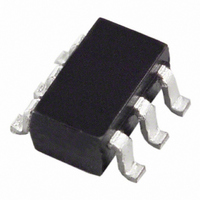
AD7414ART-1500RL7 Analog Devices Inc, AD7414ART-1500RL7 Datasheet - Page 14

AD7414ART-1500RL7
Manufacturer Part Number
AD7414ART-1500RL7
Description
IC SENSOR TEMP 10BIT SOT23-6 TR
Manufacturer
Analog Devices Inc
Datasheet
1.AD7415ARTZ-0500RL7.pdf
(20 pages)
Specifications of AD7414ART-1500RL7
Rohs Status
RoHS non-compliant
Function
Temp Monitoring System (Sensor)
Topology
ADC, Comparator, Register Bank
Sensor Type
Internal
Sensing Temperature
-40°C ~ 125°C
Output Type
I²C™/SMBus™
Output Alarm
No
Output Fan
No
Voltage - Supply
2.7 V ~ 5.5 V
Operating Temperature
-40°C ~ 125°C
Mounting Type
Surface Mount
Package / Case
SOT-23-6
AD7414/AD7415
POWER VS. THROUGHPUT
The two modes of operation for the AD7414/AD7415 produce
different power vs. throughput performances. Mode 2 is the
sleep mode of the part, and it achieves the optimum power
performance.
Mode 1
In this mode, continuous conversions are performed at a rate of
approximately one every 800 ms. Figure 14 shows the times and
currents involved with this mode of operation for a 5 V supply.
At 5 V, the current consumption for the part when converting is
1.1 mA typically, and the quiescent current is 188 μA typically.
The conversion time of 25 μs plus power-up time of typically
4 μs contributes 199.3 nW to the overall power dissipation in
the following way:
The contribution to the total power dissipated by the remaining
time is 939.96 μW.
Thus the total power dissipated during each cycle is
I
Mode 2
In this mode, the part is totally powered down. All circuitry
except the serial interface is switched off. The most power
efficient way of operating in this mode is to use the one-shot
method. Write to the configuration register and set the one-shot
bit to a 1. The part powers up in approximately 4 μs and then
performs a conversion. Once the conversion is finished, the
device powers down again until the PD bit in the configuration
register is set to 0 or the one-shot bit is set to 1. Figure 15 shows
the same timing as Figure 14 in mode 1; a one-shot is initiated
every 800 ms. If we take the voltage supply to be 5 V, we can
work out the power dissipation in the following way. The
current consumption for the part when converting is 1.1 mA
typically, and the quiescent current is 800 nA typically. The
conversion time of 25 μs plus the power-up time of typically
4 μs contributes 199.3 nW to the overall power dissipation in
the following way:
DD
(29 μs/800 ms) × (5 × 1.1 mA) = 199.3 nW
(799.97 ms/800 ms) × (5 × 1.1 μA) = 199.3 μW
199.3 nW + 939.96 μW = 940.16 μW
(29 μs/800 ms) × (5 V × 1.1 mA) = 199.3 nW
1.1mA
Figure 14. Mode 1 Power Dissipation
800ms
TIME
188μA
29μs
Rev. F | Page 14 of 20
The contribution to the total power dissipated by the remaining
time is 3.9 μW.
Thus the total power dissipated during each cycle is:
I
MOUNTING THE AD7414/AD7415
The AD7414/AD7415 can be used for surface or air tempera-
ture sensing applications. If the device is cemented to a surface
with thermally conductive adhesive, the die temperature is
within about 0.1°C of the surface temperature, due to the
device’s low power consumption. Care should be taken to
insulate the back and leads of the device from the air if the
ambient air temperature is different from the surface
temperature being measured.
The ground pin provides the best thermal path to the die, so the
temperature of the die is close to that of the printed circuit
ground track. Care should be taken to ensure that this is in
good thermal contact with the surface being measured.
As with any IC, the AD7414/AD7415 and their associated
wiring and circuits must be kept free from moisture to prevent
leakage and corrosion, particularly in cold conditions where
condensation is more likely to occur. Water-resistant varnishes
and conformal coatings can be used for protection. The small
size of the AD7414/AD7415 packages allows them to be
mounted inside sealed metal probes, which provide a safe
environment for the devices.
SUPPLY DECOUPLING
The AD7414/AD7415 should at least be decoupled with a 0.1μF
ceramic capacitor between V
important if the AD7414/AD7415 are mounted remote from
the power supply.
DD
(799.971 ms/800 ms) × (5 V × 800 nA) = 3.9 μW
199.3 nW + 3.9 μW = 940.16 μW
1.1mA
Figure 15. Mode 2 Power Dissipation
800ms
TIME
800nA
DD
and GND. This is particularly
29μs


