ADT7476AARQZ-REEL ON Semiconductor, ADT7476AARQZ-REEL Datasheet - Page 55
ADT7476AARQZ-REEL
Manufacturer Part Number
ADT7476AARQZ-REEL
Description
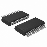
IC REMOTE THERMAL CTRLR 24-QSOP
Manufacturer
ON Semiconductor
Series
dBCool®r
Datasheet
1.ADT7476AARQZ.pdf
(67 pages)
Specifications of ADT7476AARQZ-REEL
Function
Fan Control, Temp Monitor
Topology
ADC, Comparator, Fan Speed Counter, Multiplexer, Register Bank
Sensor Type
External & Internal
Sensing Temperature
-40°C ~ 125°C, External Sensor
Output Type
SMBus™
Output Alarm
No
Output Fan
Yes
Voltage - Supply
3 V ~ 3.6 V
Operating Temperature
-40°C ~ 125°C
Mounting Type
Surface Mount
Package / Case
24-QSOP
Lead Free Status / RoHS Status
Lead free / RoHS Compliant


1. These registers become read-only when the Configuration Register 1 lock bit is set to 1. Any subsequent attempts to write to these registers fail.
Table 30. PWM Configuration Registers
Bit No.
[2:0]
[7:5]
Register Address
[3]
[4]
0x5C
0x5D
0x5E
Name
BHVR
SPIN
RES
INV
R/W (Note 1)
R/W
R/W
R/W
R/W
R/W
R/W
R/W
N/A
These bits control the startup timeout for PWMx. The PWM output stays high until two valid
TACH rising edges are seen from the fan. If there is not a valid TACH signal during the fan
TACH measurement directly after the fan startup timeout period, the TACH measurement
reads 0xFFFF and Interrupt Status Register 2 reflects the fan fault. If the TACH minimum high
and low bytes contain 0xFFFF or 0x0000, the Interrupt Status Register 2 bit is not set, even if
the fan has not started.
000 = No startup timeout
001 = 100 ms
010 = 250 ms (default)
011 = 400 ms
100 = 667 ms
101 = 1 sec
110 = 2 sec
111 = 4 sec
Reserved. Do not write to this bit.
This bit inverts the PWM output. The default is 0, which corresponds to a logic high output for
100% duty cycle. Setting this bit to 1 inverts the PWM output, so 100% duty cycle
corresponds to a logic low output.
These bits assign each fan to a particular temperature sensor for localized cooling.
000 = Remote 1 temperature controls PWMx (automatic fan control mode).
001 = Local temperature controls PWMx (automatic fan control mode).
010 = Remote 2 temperature controls PWMx (automatic fan control mode).
011 = PWMx runs full speed (default).
100 = PWMx disabled.
101 = Fastest speed calculated by local and Remote 2 temperature controls PWMx.
110 = Fastest speed calculated by all three temperature channel controls PWMx.
111 = Manual mode. PWM current duty cycle registers (0x30 to 0x32) become writable.
http://onsemi.com
PWM1 configuration
PWM2 configuration
PWM3 configuration
Description
55
Description
Power−On Default
0x62
0x62
0x62
Related parts for ADT7476AARQZ-REEL
Image
Part Number
Description
Manufacturer
Datasheet
Request
R

Part Number:
Description:
Dbcool Remote Thermal Controller And Voltage Monitor
Manufacturer:
Analog Devices, Inc.
Datasheet:

Part Number:
Description:
ON Semiconductor [VOLTAGE REGULATOR]
Manufacturer:
ON Semiconductor
Datasheet:
Part Number:
Description:
357-036-542-201 CARDEDGE 36POS DL .156 BLK LOPRO
Manufacturer:
ON Semiconductor
Datasheet:
Part Number:
Description:
357-036-542-201 CARDEDGE 36POS DL .156 BLK LOPRO
Manufacturer:
ON Semiconductor
Datasheet:
Part Number:
Description:
357-036-542-201 CARDEDGE 36POS DL .156 BLK LOPRO
Manufacturer:
ON Semiconductor
Datasheet:
Part Number:
Description:
357-036-542-201 CARDEDGE 36POS DL .156 BLK LOPRO
Manufacturer:
ON Semiconductor
Datasheet:
Part Number:
Description:
357-036-542-201 CARDEDGE 36POS DL .156 BLK LOPRO
Manufacturer:
ON Semiconductor
Datasheet:
Part Number:
Description:
357-036-542-201 CARDEDGE 36POS DL .156 BLK LOPRO
Manufacturer:
ON Semiconductor
Datasheet:
Part Number:
Description:
357-036-542-201 CARDEDGE 36POS DL .156 BLK LOPRO
Manufacturer:
ON Semiconductor
Datasheet:
Part Number:
Description:
357-036-542-201 CARDEDGE 36POS DL .156 BLK LOPRO
Manufacturer:
ON Semiconductor
Datasheet:
Part Number:
Description:
357-036-542-201 CARDEDGE 36POS DL .156 BLK LOPRO
Manufacturer:
ON Semiconductor
Datasheet:
Part Number:
Description:
357-036-542-201 CARDEDGE 36POS DL .156 BLK LOPRO
Manufacturer:
ON Semiconductor
Datasheet:
Part Number:
Description:
Manufacturer:
ON Semiconductor
Datasheet:
Part Number:
Description:
Manufacturer:
ON Semiconductor
Datasheet: