ADR360AUJZ-REEL7 Analog Devices Inc, ADR360AUJZ-REEL7 Datasheet - Page 10
ADR360AUJZ-REEL7
Manufacturer Part Number
ADR360AUJZ-REEL7
Description
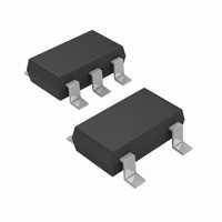
IC VREF LP 2.048V 25PPM TSOT23-5
Manufacturer
Analog Devices Inc
Specifications of ADR360AUJZ-REEL7
Temperature Coefficient
25ppm/°C
Reference Type
Series
Voltage - Output
2.048V
Tolerance
±0.29%
Voltage - Input
2.35 ~ 15 V
Number Of Channels
1
Current - Quiescent
190µA
Current - Output
5mA
Operating Temperature
-40°C ~ 125°C
Mounting Type
Surface Mount
Package / Case
TSOT-23-5, TSOT-5, TSOP-5
Topology
Series
Input Voltage
2.45V To 15V
Reference Voltage
2.048V
Reference Voltage Tolerance
6mV
Voltage Reference Case Style
SOT-23
No. Of Pins
5
Operating
RoHS Compliant
Lead Free Status / RoHS Status
Lead free / RoHS Compliant
Current - Cathode
-
Lead Free Status / RoHS Status
Lead free / RoHS Compliant


ADR360/ADR361/ADR363/ADR364/ADR365/ADR366
TERMINOLOGY
Temperature Coefficient
The change of output voltage with respect to operating
temperature changes normalized by the output voltage at 25°C.
This parameter is expressed in ppm/°C and can be determined
by
where:
V
V
V
Line Regulation
The change in output voltage due to a specified change in input
voltage. This parameter accounts for the effects of self-heating.
Line regulation is expressed in either percent per volt, parts-
per-million per volt, or microvolts per volt change in input
voltage.
Load Regulation
The change in output voltage due to a specified change in load
current. This parameter accounts for the effects of self-heating.
Load regulation is expressed in either microvolts per
milliampere, parts-per-million per milliampere, or ohms of dc
output resistance.
Long-Term Stability
Typical shift of output voltage at 25°C on a sample of parts
subjected to a test of 1,000 hours at 25°C.
where:
V
V
O
O
O
O
O
(25°C) = V
( T
( T
( t
( t
∆ V
0
1
TCV
ΔV
1
2
) = V
) = V
) = V
) = V
O
O
O
= V
[
ppm
O
O
[
O
O
ppm/
at 25°C at Time 0.
at 25°C after 1,000 hours operation at 25°C.
at Temperature 1.
at Temperature 2.
O
O
( t
]
at 25°C.
0
=
) – V
°
C
⎛
⎜
⎜
⎝
V
]
O
=
O
( )
( t
V
t
V
0
1
O
O
)
–V
V
(
( )
t
25
O
0
O
( )
T
°
( )
C
t
2
1
)
–V
×
×
(
O
10
T
( )
2
T
–T
6
1
⎞
⎟
⎟
⎠
1
)
×
10
6
Rev. 0 | Page 10 of 20
Thermal Hysteresis
The change of output voltage after the device is cycled through
temperature from +25°C to –40°C to +125°C and back to
+25°C. This is a typical value from a sample of parts put
through such a cycle.
where:
V
V
+125°C and back to +25°C.
NOTES
Input Capacitor
Input capacitors are not required on the ADR36x. There is no
limit for the value of the capacitor used on the input, but a 1 µF
to 10 µF capacitor on the input improves transient response in
applications where the supply suddenly changes. An additional
0.1 µF capacitor in parallel also helps reduce noise from the
supply.
Output Capacitor
The ADR36x does not require output capacitors for stability
under any load condition. An output capacitor, typically 0.1 µF,
filters out any low level noise voltage and does not affect the
operation of the part. On the other hand, the load transient
response can improve with an additional 1 µF to 10 µF output
capacitor in parallel. A capacitor here acts as a source of stored
energy for a sudden increase in load current. The only
parameter that degrades by adding an output capacitor is the
turn-on time. The degradation depends on the size of the
capacitor chosen.
O
O_TC
(25°C) = V
V
V
= V
O_HYS
O_HYS
O
at 25°C after temperature cycle at +25°C to –40°C to
= V
[
ppm
O
O
at 25°C.
(25°C) – V
]
=
V
O
(
25
V
O
°
O_TC
(
C
25
)
–
°
C
V
)
O_TC
×
10
6
Related parts for ADR360AUJZ-REEL7
Image
Part Number
Description
Manufacturer
Datasheet
Request
R

Part Number:
Description:
IC VREF LP 2.048V 25PPM TSOT23-5
Manufacturer:
Analog Devices Inc
Datasheet:

Part Number:
Description:
Low Power, Low Noise Voltage References with Sink/Source Capability
Manufacturer:
AD [Analog Devices]
Datasheet:

Part Number:
Description:
±1.7g Dual-Axis IMEMS Accelerometer Evaluation Board
Manufacturer:
Analog Devices Inc
Datasheet:

Part Number:
Description:
Inertial Sensor Evaluation System
Manufacturer:
Analog Devices Inc
Datasheet:
Part Number:
Description:
Manufacturer:
Analog Devices Inc
Datasheet:
Part Number:
Description:
Manufacturer:
Analog Devices Inc
Datasheet:
Part Number:
Description:
Manufacturer:
Analog Devices Inc
Datasheet:
Part Number:
Description:
Manufacturer:
Analog Devices Inc
Datasheet:
Part Number:
Description:
Manufacturer:
Analog Devices Inc
Datasheet:
Part Number:
Description:
Manufacturer:
Analog Devices Inc
Datasheet:
Part Number:
Description:
Manufacturer:
Analog Devices Inc
Datasheet:
Part Number:
Description:
Manufacturer:
Analog Devices Inc
Datasheet:
Part Number:
Description:
Manufacturer:
Analog Devices Inc
Datasheet: