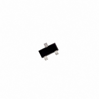
TS824AILT-2.5 STMicroelectronics, TS824AILT-2.5 Datasheet - Page 2

TS824AILT-2.5
Manufacturer Part Number
TS824AILT-2.5
Description
IC VREF SHUNT HI THERMAL SOT-23
Manufacturer
STMicroelectronics
Datasheet
1.TS824ILT-2.5.pdf
(5 pages)
Specifications of TS824AILT-2.5
Reference Type
Shunt
Voltage - Output
2.5V
Tolerance
±0.5%
Temperature Coefficient
50ppm/°C
Number Of Channels
1
Current - Cathode
50µA
Current - Output
15mA
Operating Temperature
-40°C ~ 85°C
Mounting Type
Surface Mount
Package / Case
SOT-23-3, TO-236-3, Micro3™, SSD3, SST3
Product
Voltage References
Topology
Shunt References
Output Voltage
2.5 V
Initial Accuracy
0.5 %
Average Temperature Coefficient (typ)
50 PPM / C
Shunt Current (max)
15 mA
Maximum Operating Temperature
+ 85 C
Minimum Operating Temperature
- 40 C
Mounting Style
SMD/SMT
Shunt Current (min)
0.06 mA
Lead Free Status / RoHS Status
Lead free / RoHS Compliant
Voltage - Input
-
Current - Quiescent
-
Lead Free Status / Rohs Status
Lead free / RoHS Compliant
Available stocks
Company
Part Number
Manufacturer
Quantity
Price
Part Number:
TS824AILT-2.5
Manufacturer:
ST
Quantity:
20 000
TS824-2.5
ABSOLUTE MAXIMUM RATINGS
OPERATING CONDITIONS
ELECTRICAL CHARACTERISTICS (note 3)
T
2/5
Note 1: The maximum power dissipation must be derated at high temperature. It can be calculated using T
perature), R
temperature is P
Note 2: The Human Body Model (HBM) is defined as a 100pF capacitor discharge through a 1.5k
Note 3: Limits are 100% production tested at 25°C. Limits over temperature are guaranteed through correlation and by design.
Note 4: The total tolerance within the industrial range, where the maximum T versus 25°C is 65°C, is explained hereafter:
Symbol
Symbol
Symbol
amb
V
V
I
T
ESD
T
R
K
KMIN
T
I
V
E
I
K
K
P
Lead
max
oper
min
I
VH
I
KA
Std
K
N
K
F
/ I
= 25°C (unless otherwise specified)
/ T
D
K
The Machine Mode (MM) is defined as a 200pF capacitor discharge directly into each pins.
1 % + ( 50 ppm/°C x 65°C) =
Reverse Breakdown Voltage
Reverse Breakdown Voltage Tolerance
Minimum Operating Current
Average Temperature Coefficient (note
5)
Reverse Breakdown Voltage Change
with Operating Current Range
Static Impedance
Long Term Stability
Wide Band Noise
THJA
Reverse Breakdown Current
Forward Current
Power Dissipation (note1)
Storage Temperature
Human Body Model (HBM) (note2)
Machine Model (MM) (note 2)
Lead Temperature (soldering, 10 seconds)
Minimum Operating Current
Maximum Operating Current
Operating Free Air Temperature Range
(Thermal resistance junction to ambient) and T
DMAX
= (T
JMAX
Parameter
- T
A
) / R
THJA.
1.325 %
Parameter
Parameter
SOT23-3
R
THJA
is 340°C/W for the SOT23-3 package.
I
I
I
-40°C < T
I
-40°C < T
T
-40°C < T
I
I
-40°C < T
1mA < I
-40°C < T
-40°C < T
-40°C < T
I
I
100Hz < f < 10kHz
K
K
K
K
K
KMIN
K
K
amb
I
I
K
K
= 100 A, ±0.5%
= 100 A, ±1%
= 100 A, ±0.5%
= 100 A, ±1%
= 100 A
= 100 A, t = 1000hrs
= 100 A
A
= I
= 1mA to 15mA
(Ambient temperature). The maximum power dissipation formula at any
= 25°C
< I
KMIN
K
K
Test Condition
< 1mA
< 15mA
amb
amb
amb
amb
amb
amb
amb
to 1mA
< +85°C
< +85°C
< +85°C
< +85°C
< +85°C
< +85°C
< +85°C
2.4875 2.500 2.5125
2.475
resistor into each pin.
-12.5
Min.
-20
-25
-33
-65 to +150
-40 to +85
Value
Value
JMAX
360
200
260
20
10
60
15
2
2.500
Typ.
120
350
0.4
4.5
0.4
0.3
50
(maximum junction tem-
2.525
+12.5
Max.
+20
+25
+33
1.2
1.2
0.6
0.7
60
65
50
10
1
8
1
ppm/°C
nV/ Hz
Unit
Unit
Unit
ppm
mW
mV
mV
mA
mA
mA
°C
kV
°C
°C
V
V
A
A


