GNM212R61A225MA01D Murata Electronics North America, GNM212R61A225MA01D Datasheet - Page 148
GNM212R61A225MA01D
Manufacturer Part Number
GNM212R61A225MA01D
Description
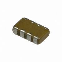
CAP 2-ARRAY 2.2UF 10V X5R 0805
Manufacturer
Murata Electronics North America
Series
GNMr
Datasheet
1.GNM212R61A225MA01D.pdf
(151 pages)
Specifications of GNM212R61A225MA01D
Capacitance
2.2µF
Voltage - Rated
10V
Dielectric Material
Ceramic
Number Of Capacitors
2
Circuit Type
Isolated
Temperature Coefficient
X5R
Tolerance
±20%
Mounting Type
Surface Mount
Package / Case
0805 (2012 Metric)
Height
0.033" (0.85mm)
Size / Dimension
0.079" L x 0.049" W (2.00mm x 1.25mm)
Lead Free Status / RoHS Status
Lead free / RoHS Compliant
Other names
GNM212R61A225MA01


23
!Note
• This PDF catalog is downloaded from the website of Murata Manufacturing co., ltd. Therefore, it’s specifications are subject to change or our products in it may be discontinued without advance notice. Please check with our
• This PDF catalog has only typical specifications because there is no space for detailed specifications. Therefore, please approve our product specifications or transact the approval sheet for product specifications before ordering.
sales representatives or product engineers before ordering.
!Note
2. Mounting of Chips
3. Soldering
(1) Limit of losing effective area of the terminations and
(2) Flux
146
Notice
Thickness of adhesives applied
Keep thickness of adhesives applied (50-105 m or more)
to reinforce the adhesive contact considering the
thickness of the termination or capacitor (20-70 m) and
the land pattern (30-35 m).
Mechanical shock of the chip placer
When the positioning claws and pick-up nozzle are worn,
the load is applied to the chip while positioning is
concentrated in one position, thus causing cracks,
breakage, faulty positioning accuracy, etc.
Careful checking and maintenance are necessary to
prevent unexpected trouble.
An excessively low bottom dead point of the suction
nozzle imposes great force on the chip during mounting,
causing cracked chips. Please set the suction nozzle's
bottom dead point on the upper surface of the board.
conditions needed for soldering.
Please use it after confirming there is no problem in the
reliability of the product beforehand with the intended
equipment. The residue of flux might cause a decrease in
nonconductivity and the corrosion of an external
electrode, etc.
Continued from the preceding page.
Depending on the conditions of the soldering
temperature and/or immersion (melting time),
effective areas may be lost in some part of the
terminations.
To prevent this, be careful in soldering so that any
possible loss of the effective area on the terminations
will securely remain at a maximum of 25% on all
edge length A-B-C-D-A of part with A, B, C, D, shown
in the Figure below.
• Please read rating and !CAUTION (for storage, operating, rating, soldering, mounting and handling) in this catalog to prevent smoking and/or burning, etc.
• This catalog has only typical specifications because there is no space for detailed specifications. Therefore, please approve our product specifications or transact the approval sheet for product specifications before ordering.
B
C
A
D
Termination
Continued on the following page.
C02E.pdf
07.2.6
Related parts for GNM212R61A225MA01D
Image
Part Number
Description
Manufacturer
Datasheet
Request
R

Part Number:
Description:
BUZZER PIEZO 25VP-P SMD
Manufacturer:
Murata Electronics North America

Part Number:
Description:
CAP 4-ARRAY 680PF 100V X7R 1206
Manufacturer:
Murata Electronics North America
Datasheet:
Part Number:
Description:
CAP 4-ARRAY 1000PF 100V X7R 1206
Manufacturer:
Murata Electronics North America
Datasheet:
Part Number:
Description:
CAP 4-ARRAY 1800PF 100V X7R 1206
Manufacturer:
Murata Electronics North America
Datasheet:
Part Number:
Description:
CAP 4-ARRAY 68000PF 16V X7R 1206
Manufacturer:
Murata Electronics North America
Datasheet:

Part Number:
Description:
CAP CER 1000PF 50V 10% X7R 0402
Manufacturer:
Murata Electronics North America
Datasheet:
Part Number:
Description:
CAP CER 10000PF 16V 10% X7R 0402
Manufacturer:
Murata Electronics North America
Datasheet:

Part Number:
Description:
CAP 5.5-25PF 2.5X3.2MM SMD
Manufacturer:
Murata Electronics North America
Datasheet:

Part Number:
Description:
CAP 4.5-20PF 2.5X3.2MM SMD
Manufacturer:
Murata Electronics North America
Datasheet:

Part Number:
Description:
CAP 5.0-20PF 3.2X4.5MM SMD RED
Manufacturer:
Murata Electronics North America
Datasheet:

Part Number:
Description:
CAP 2.0-6.0PF 3.2X4.5MM SMD BLU
Manufacturer:
Murata Electronics North America
Datasheet:

Part Number:
Description:
CAP 1.4-3.0PF 3.2X4.5MM SMD BRN
Manufacturer:
Murata Electronics North America
Datasheet:

Part Number:
Description:
CAP 3.0-10PF 3.2X4.5MM SMD WHT
Manufacturer:
Murata Electronics North America
Datasheet:

Part Number:
Description:
CAP 2.0-6.0PF 4X4.5MM TOPADJ BLU
Manufacturer:
Murata Electronics North America
Datasheet:

Part Number:
Description:
CAP 8.5-40PF 4X4.5MM TOPADJ YEL
Manufacturer:
Murata Electronics North America
Datasheet: