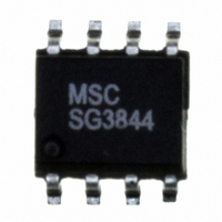
SG3844DM Microsemi Analog Mixed Signal Group, SG3844DM Datasheet - Page 2

SG3844DM
Manufacturer Part Number
SG3844DM
Description
IC PWM CURRENT MODE 8SOIC
Manufacturer
Microsemi Analog Mixed Signal Group
Datasheet
1.SG3845M.pdf
(12 pages)
Specifications of SG3844DM
Pwm Type
Current Mode
Number Of Outputs
1
Frequency - Max
500kHz
Duty Cycle
50%
Voltage - Supply
8.2 V ~ 30 V
Buck
Yes
Boost
No
Flyback
No
Inverting
No
Doubler
No
Divider
No
Cuk
No
Isolated
Yes
Operating Temperature
0°C ~ 70°C
Package / Case
8-SOIC
Frequency-max
500kHz
Lead Free Status / RoHS Status
Lead free / RoHS Compliant
Available stocks
Company
Part Number
Manufacturer
Quantity
Price
Company:
Part Number:
SG3844DM
Manufacturer:
Microsemi Analog Mixed Signal
Quantity:
1 791
2
SG1844/SG1845 Series
Supply Voltage (I
Supply Voltage (Low Impedance Source) ........................................................ 30V
Output Current (Peak) ....................................................................................... ±1A
Output Current (Continuous) ....................................................................... 350mA
Output Energy (Capacitive Load) ....................................................................... 5µJ
Analog Inputs (V
Error Amp Output Sink Current ..................................................................... 10mA
Operating Junction Temperature
Storage Temperature Range .......................................................... -65°C to +150°C
Lead Temperature (Soldering, 10 Seconds) .................................................. 300°C
RoHS / Pb-free Peak Package Solder Reflow Temp. (40 second max. exposure)............................... 260°C (+0, -5)
Note 1. Exceeding these ratings could cause damage to the device.
Note 2. All voltages are with respect to Pin 5. All currents are positive into the specified
M PACKAGE:
N PACKAGE:
DM PACKAGE:
D PACKAGE:
Y PACKAGE:
J PACKAGE:
F PACKAGE:
L PACKAGE:
Junction Temperature Calculation: T
The θ
system. All of the above assume no ambient airflow.
THERMAL RESISTANCE-JUNCTION TO AMBIENT, θ θ θ θ θ
THERMAL RESISTANCE-JUNCTION TO AMBIENT, θ θ θ θ θ
THERMAL RESISTANCE-JUNCTION TO AMBIENT, θ θ θ θ θ
THERMAL RESISTANCE-JUNCTION TO AMBIENT, θ θ θ θ θ
THERMAL RESISTANCE-JUNCTION TO AMBIENT, θ θ θ θ θ
THERMAL RESISTANCE-JUNCTION TO AMBIENT, θ θ θ θ θ
THERMAL RESISTANCE-JUNCTION TO CASE, θ θ θ θ θ
THERMAL RESISTANCE-JUNCTION TO AMBIENT, θ θ θ θ θ
THERMAL RESISTANCE-JUNCTION TO CASE, θ θ θ θ θ
THERMAL RESISTANCE-JUNCTION TO AMBIENT, θ θ θ θ θ
Hermetic (J, Y, F, L Packages) ................................................................... 150°C
Plastic (N, M, D, DM Packages) ................................................................ 150°C
JA
numbers are guidelines for the thermal performance of the device/pc-board
A B S O L U T E M A X I M U M R AT I N G S
terminal.
FB
CC
, I
< 30mA) ............................................................... Self Limiting
SENSE
) ................................................................ -0.3V to +6.3V
T H E R M A L D ATA
P R O D U C T D A T A B O O K 1 9 9 6 / 1 9 9 7
J
= T
C
A
U R R E N T
+ (P
P
R O D U C T I O N
D
JC
JC
x θ
JA
JA
JA
JA
JA
JA
JA
JA
JA
).
- M
O D E
(Notes 1 & 2)
P W M C
D
165°C/W
120°C/W
130°C/W
145°C/W
120°C/W
95°C/W
65°C/W
80°C/W
80°C/W
35°C/W
A T A
O N T R O L L E R
S
H E E T
1. COM
2. V
3. I
4. R
5. OWER GND
4
5
6
7
8
SENSE
M Package: RoHS / Pb-free 100% Matte Tin Lead Finish
FB
T
N Package: RoHS / Pb-free 100% Matte Tin Lead Finish
/C
T
3
9
10
PACKAGE PIN OUTS
2
RoHS / Pb-free 100% Matte Tin Lead Finish
COM
RoHS / Pb-free 100% Matte Tin Lead Finish
COM
11
R
1 20 19
N.C.
N.C.
I
N.C.
R
T
COM
SENSE
COM
I
/C
SENSE
T
V
R
/C
R
V
12 13
I
N.C.
N.C.
I
N.C.
FB
SENSE
T
T
M & Y PACKAGE
SENSE
/C
T
FB
/C
V
V
J & N PACKAGE
T
DM PACKAGE
FB
FB
T
T
D PACKAGE
F PACKAGE
L PACKAGE
(Top View)
(Top View)
(Top View)
(Top View)
(Top View)
(Top View)
1
2
3
4
1
2
3
4
5
6
7
1
2
3
4
5
1
2
3
4
5
6
7
1
2
3
4
18
17
16
15
14
14
13
12
11
10
10
8
7
6
5
14
13
12
11
10
9
8
8
7
6
5
9
8
9
8
7
6
1. N.C.
2. N.C.
3. COM .
4. N.C.
5. V
6. N.C.
7. I
8. R
9. N.C.
10. N.C.
V
V
OUT UT
GND
V
N.C.
V
V
OUT UT
GROUND
REF
CC
V
V
OUT UT
GND
SENSE
OWER GND
REF
CC
C
V
N.C.
V
V
OUT UT
GND
FB
T
REF
CC
/C
WR GND
REF
CC
C
T
Copyright © 2000
Rev. 1.6c
10.V
9. V
8. V
7. OUT UT
6. GND
11. N.C.
12. WR GND
13. GND
14. N.C.
15. OUT UT
16. N.C.
17. V
18. V
19. N.C.
20. V
REF
CC
C
C
CC
REF


