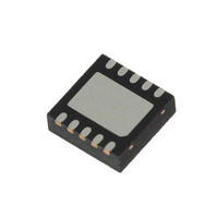
L6728AHTR STMicroelectronics, L6728AHTR Datasheet - Page 12

L6728AHTR
Manufacturer Part Number
L6728AHTR
Description
IC CTLR PWM SGL PHASE 10-VFQFPN
Manufacturer
STMicroelectronics
Datasheet
1.L6728AHTR.pdf
(33 pages)
Specifications of L6728AHTR
Pwm Type
Voltage Mode
Number Of Outputs
1
Frequency - Max
660kHz
Duty Cycle
67%
Voltage - Supply
5 V ~ 12 V
Buck
Yes
Boost
No
Flyback
No
Inverting
No
Doubler
No
Divider
No
Cuk
No
Isolated
No
Operating Temperature
-40°C ~ 125°C
Package / Case
10-VFQFN, 10-VFQFPN
Frequency-max
660kHz
Lead Free Status / RoHS Status
Lead free / RoHS Compliant
Other names
497-8977-2
Available stocks
Company
Part Number
Manufacturer
Quantity
Price
Company:
Part Number:
L6728AHTR
Manufacturer:
PHI
Quantity:
1 800
Company:
Part Number:
L6728AHTR
Manufacturer:
STMicroelectronics
Quantity:
10 000
Part Number:
L6728AHTR
Manufacturer:
ST
Quantity:
20 000
Over-current protection
7
7.1
12/33
Over-current protection
The over-current function protects the converter from a shorted output or overload, by
sensing the output current information across the low side MOSFET drain-source on-
resistance, R
avoiding the use of expensive and space-consuming sense resistors.
The low side R
node when LS MOSFET is turned on with the programmed OCP thresholds voltages,
internally held. If the monitored voltage is bigger than these thresholds, an over-current
event is detected.
For maximum safety and load protection, L6728AH implements a dual level over-current
protection system:
●
●
When over-current protection is triggered, the device turns off both LS and HS MOSFETs in
a latched condition. To recover from over-current protection triggered condition, V
supply must be cycled.
Over-current threshold setting
L6728AH allows to easily program a 1
550 mV, simply by adding a resistor (R
will be automatically set accordingly.
During a short period of time (about 5 ms) following
internal 10 µA current (I
across R
level over-current threshold. The OC setting procedure overall time length is about 5 ms.
Connecting a R
threshold will be:
the programmed 2
In case R
values: an internal safety clamp on LGATE is triggered as soon as LGATE voltage reaches
600 mV, setting the maximum threshold and suddenly ending OC setting phase.
1
PHASE exceeds this threshold, a 1
events are detected in four consecutive switching cycles, over-current protection will be
triggered.
2
threshold multiplied by a factor 1.5. If the monitored voltage on PHASE exceeds this
threshold, over-current protection will be triggered immediately.
st
nd
level threshold: it is the user externally set threshold. If the monitored voltage on
level threshold: it is an internal threshold whose value is equal to 1
OCSET
OCSET
DS(on)
DS(on)
. This voltage drop will be sampled and internally held by the device as 1
OCSET
is not connected, the device sets the OCP thresholds to the maximum
nd
. This method reduces cost and enhances converter efficiency by
level threshold will be:
current sense is implemented by comparing the voltage at the PHASE
resistor between LGATE and GND, the programmed 1
OCSET
I
OCth2
) is sourced from LGATE pin, determining a voltage drop
I
Doc ID 15726 Rev 1
OCth1
=
st
OCSET
=
1.5
st
level over-current threshold ranging from 50 mV to
I
------------------------------------------- -
level over-current is detected. If four 1
OCSET
⋅
) between LGATE and GND. 2
I
------------------------------------------- -
OCSET
R
dsON
⋅
R
R
V
dsON
CC
⋅
OCSET
R
rising over UVLO threshold, an
OCSET
nd
st
level threshold
st
level
level
st
CC
level OC
L6728AH
power
st


