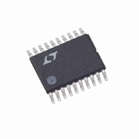
LT3570EFE#TRPBF Linear Technology, LT3570EFE#TRPBF Datasheet - Page 12

LT3570EFE#TRPBF
Manufacturer Part Number
LT3570EFE#TRPBF
Description
IC PWM BUCK BST DIV CM 20TSSOP
Manufacturer
Linear Technology
Datasheet
1.LT3570EFEPBF.pdf
(20 pages)
Specifications of LT3570EFE#TRPBF
Topology
Step-Down (Buck) (1), Step-Up (Boost) (1), Linear (LDO) (1)
Function
Automotive
Number Of Outputs
3
Frequency - Switching
500kHz ~ 2.1MHz
Voltage/current - Output 1
Adj to 0.8V, 1.5A
Voltage/current - Output 2
Adj to 0.8V, 1.5A
Voltage/current - Output 3
Controller
W/led Driver
No
W/supervisor
No
W/sequencer
No
Voltage - Supply
2.5 V ~ 36 V
Operating Temperature
-40°C ~ 125°C
Mounting Type
*
Package / Case
20-TSSOP Exposed Pad, 20-eTSSOP, 20-HTSSOP
Frequency-max
2.75MHz
Duty Cycle
95%
Pwm Type
Current Mode
Buck
Yes
Boost
Yes
Flyback
No
Inverting
No
Doubler
No
Divider
Yes
Cuk
No
Isolated
No
Lead Free Status / RoHS Status
Lead free / RoHS Compliant
Available stocks
Company
Part Number
Manufacturer
Quantity
Price
LT3570
APPLICATIONS INFORMATION
and small circuit size, are therefore an option. You can
estimate output ripple with the following equations:
and
The RMS content of this ripple is very low so the RMS
current rating of the output capacitor is usually not of
concern. It can be estimated with the formula:
Another constraint on the output capacitor is that it must
have greater energy storage than the inductor; if the stored
energy in the inductor transfers to the output, the resulting
voltage step should be small compared to the regulation
voltage. For a 5% overshoot, this requirement indicates:
The low ESR and small size of ceramic capacitors make
them the preferred type for LT3570 applications. Not all
ceramic capacitors are the same, however. Many of the
higher value capacitors use poor dielectrics with high
temperature and voltage coeffi cients. In particular, Y5V
and Z5U types lose a large fraction of their capacitance
with applied voltage and at temperature extremes. Because
loop stability and transient response depend on the value
of C
types.
Electrolytic capacitors are also an option. The ESRs of
most aluminum electrolytic capacitors are too large to
deliver low output ripple. Tantalum, as well as newer,
lower ESR organic electrolytic capacitors intended for
power supply use are suitable. Chose a capacitor with a
low enough ESR for the required output ripple. Because
the volume of the capacitor determines its ESR, both the
size and the value will be larger than a ceramic capacitor
that would give similar ripple performance. One benefi t
is that the larger capacitance may give better transient
12
V
and aluminum)
I
C
V
C(RMS)
OUT
RIPPLE
RIPPLE
OUT
, this loss may be unacceptable. Use X7R and X5R
> 10 • L •
= ΔI
=
=
ΔI
8 • f • C
L2
12
L2
ΔI
• ESR for electrolytic capacitors (tantalum
⎛
⎝ ⎜
L2
V
I
OUT
LIM2
OUT2
for ceramic capacitors
⎞
⎠ ⎟
2
re sponse for large changes in load current. Table 2 lists
several capacitor vendors.
Table 2. Low ESR Surface Mount Capacitors
VENDOR
Taiyo Yuden
AVX
Kemet
Sanyo
Panasonic
TDK
Boost Output Capacitor Selection
Low ESR capacitors should be used at the output to
minimize the output ripple voltage. Multilayer ceramic
capacitors are the best choice, as they have a very low
ESR and are available in very small packages. Always use
a capacitor with a suffi cient voltage rating. Boost regula-
tors have large RMS ripple current in the output capacitor,
which must be rated to handle the current. The formula
to calculate this is:
and is largest when V
and I
maximum that the output current ripple can be is ~0.75A.
Table 2 lists several capacitor vendors.
Buck Input Capacitor Selection
Bypass the input of the LT3570 circuit with a 10μF or
higher ceramic capacitor of X7R or X5R type. A lower
value or a less expensive Y5V type will work if there is
additional bypassing provided by bulk electrolytic capaci-
tors, or if the input source impedance is low. The following
paragraphs describe the input capacitor considerations
in more detail.
Step-down regulators draw current from the input supply
in pulses with very fast rise and fall times. The input ca-
pacitor is required to reduce the resulting voltage ripple
at the LT3570 input and to force this switching current
I
RIPPLE(RMS)
OUT1
are constant. With a 1.5A current limit, the
=I
OUT
TYPE
Ceramic
Ceramic
Tantalum
Tantalum
Ta Organic
Al Organic
Ta or Al Organic
Al Organic
Ceramic
IN1
1– DC1
is at its minimum value if V
DC1
= I
OUT1
SERIES
X5R, X7R
X5R, X7R
TPS
T491, T494, T495
T520
A700
POSCAP
SP CAP
X5R, X7R
V
OUT1
V
IN1
– V
IN1
OUT1
3570fb


