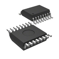
MIC2186BQS Micrel Inc, MIC2186BQS Datasheet - Page 13

MIC2186BQS
Manufacturer Part Number
MIC2186BQS
Description
IC PWM BST FLYBCK CM 16QSOP
Manufacturer
Micrel Inc
Datasheet
1.MIC2186YM.pdf
(15 pages)
Specifications of MIC2186BQS
Pwm Type
Current Mode
Number Of Outputs
1
Frequency - Max
440kHz
Duty Cycle
85%
Voltage - Supply
2.9 V ~ 14 V
Buck
No
Boost
Yes
Flyback
Yes
Inverting
No
Doubler
No
Divider
No
Cuk
No
Isolated
No
Operating Temperature
-40°C ~ 125°C
Package / Case
16-QSOP
Frequency-max
440kHz
Lead Free Status / RoHS Status
Contains lead / RoHS non-compliant
The maximum recommended output switching frequency is
600kHz. Synchronizing to higher frequencies may be pos-
sible, however there are some concerns. As the switching
frequency is increased, the switching period decreases. The
minimum on-time in the MIC2186 becomes a greater part of
the total switching period. This may prevent proper operation
as Vin approaches Vout and may also minimize the effective-
ness of the current limit circuitry. The maximum duty cycle
decreases as the sync frequency is increased. Figure 9
shows the relationship between the minimum/maximum duty
cycle and frequency.
Soft start
Soft start reduces the power supply input surge current at
start up by limiting the output voltage risetime. Input surge
current occurs when the boost converter charges up the
April 2005
MIC2186
HiDC = HIGH
HiDC = LOW
Conditions:
Conditions:
F/2 = LOW
F/2 = LOW
85
80
75
70
65
60
55
50
45
40
250 300 350 400 450 500 550 600
HiDC=H
F/2=H
HiDC=L
F/2=H
SYNC FREQUENCY (kHz)
MIC2186 Sync
MIC2186 Sync
Figure 8a.
Figure 8b.
Max. Duty Cycle
Figure 9.
vs. Frequency
HiDC=H
HiDC=L
F/2=L
F/2=L
Sync Input
(Pin 11)
Gat Drive Output
(Pin 14)
Sync Input
(Pin 11)
Gat Drive Output
(Pin 14)
13
output capacitance. Slowing the output risetime lowers the
input surge current. Soft start may also be used for power
supply sequencing. The soft start cannot control the initial
surge in current in a boost converter when Vin is applied. This
surge current is caused by the output capacitance charging
up to the input voltage. The current flows from the input
through the inductor and output diode to the output capaci-
tors.
The soft start voltage is applied directly to the PWM compara-
tor. A 5uA internal current source is used to charge up the soft
start capacitor. Either of 2 UVLO conditions will pull the soft
start capacitor low.
The part switches at a low duty cycle when the soft start pin
voltage zero. As the soft start voltage rises from 0V to 0.7V,
the duty cycle increases from the minimum duty cycle to the
operating duty cycle. The oscillator runs at the foldback
frequency until the feedback voltage rises above 0.3V. In a
boost converter the output voltage is equal to the input
voltage before the MIC2186 starts switching. If the ratio of
Vout/Vin is low, the voltage on the feedback pin will already
be greater than 0.3V and the converter begin switching at the
selected operating frequency.
The risetime of the output is dependent on the soft start
capacitor, output capacitance, input and output voltage and
load current. The scope photo in Figure 10 show the output
voltage and the soft start pin voltage at startup. The output
voltage is initially at the input voltage less a diode drop. After
the converter is enabled the output slowly rises due to the
minimum duty cycle of the controller. As the soft start voltage
increases, the output voltage rises in a controlled fashion until
the output voltage reaches the regulated value.
Voltage Setting Components
The MIC2186 requires two resistors to set the output voltage
as shown in figure 11
* When the Vdd voltage drops below its UVLO
* When the enable pin drops below its 1.5V UVLO
threshold
threshold
Figure 10.
Soft Start
M9999-042205
Micrel, Inc.
0V


