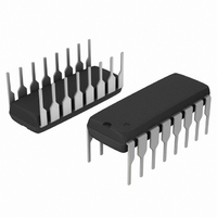
MC44604P ON Semiconductor, MC44604P Datasheet - Page 19

MC44604P
Manufacturer Part Number
MC44604P
Description
IC CTRLR PWM FREQ PULSED 16DIP
Manufacturer
ON Semiconductor
Series
GreenLine™r
Type
High Performance Pulsed Mode PWM Contollerr
Datasheet
1.MC44604P.pdf
(22 pages)
Specifications of MC44604P
Pwm Type
Current Mode
Number Of Outputs
1
Frequency - Max
250kHz
Duty Cycle
82%
Voltage - Supply
10 V ~ 15 V
Buck
No
Boost
No
Flyback
Yes
Inverting
No
Doubler
No
Divider
No
Cuk
No
Isolated
No
Operating Temperature
-25°C ~ 85°C
Package / Case
16-DIP (0.300", 7.62mm)
Frequency-max
250kHz
Input Voltage Range
18 V
Mounting Style
Through Hole
Lead Free Status / RoHS Status
Contains lead / RoHS non-compliant
Other names
MC44604POS
Available stocks
Company
Part Number
Manufacturer
Quantity
Price
Company:
Part Number:
MC44604P
Manufacturer:
ON
Quantity:
1 765
Part Number:
MC44604P
Manufacturer:
ON/安森美
Quantity:
20 000
Company:
Part Number:
MC44604P2
Manufacturer:
IR
Quantity:
6 882
change of mode, the MC44604 is first turned off so that a
new startup should be performed.
standby or in normal mode configuration.
so that, if:
− I
− I
is set (refer to Figure 40).
circuit operation in order to have the internal signals well
stabilized before the decision is taken.
That is why, as explained in the transitions §, at each
At each startup, the circuit detects if it must work in
To do that, the circuit compares the current I
According to the detected mode, the circuit configuration
This detection phase takes place during the first 5 ms of
TL431
pin15
pin15
− Pin 15 and pin 12 are kept
disconnected and so, the
E/A input receives no feed-
back (the regulation is per-
formed by comparing I
to I
regulation w)
− the soft−start is inhibited
and its capacitor is dis-
charged
− the lpmax limitation block
is activated (clamp of the
peak current)
− the level V
creased (refer to under-
voltage lockout section)
Figure 41. Standby Pin 15 Arrangement
reg
> I
< I
− refer to standby
STANDBY
det
det
R
Figure 40. Startup Operation
Opto Coupler
reg
: Standby mode
: Normal mode
YES
V
disable2
cc
gets higher than V
Z
mP
I
pin
is in-
pin 15
R
15 > I
det
V
Startup
stby
det
T
R
C
− The pin 15 is connec-
ted to pin 12 to provide
the E/A input with a feed-
back
− the standby block is in-
hibited
*
* this test is performed
during the first 5 ms of
circuit operation
init
NORMAL MODE
stup−th
NO
V
CC
R
MC44604
pin15
Pin 15
http://onsemi.com
to I
det
19
Standby Management
− the off phase during which the MC44604 is off.
− the active phase during which the MC44604 is on. At
controlled so that:
− the normal mode regulation means (error amplifier)
− the V
− the peak inductor current is forced to be constant and
where: I
− when the pin 15 current gets higher than the threshold
sequences and finally three phases can be defined (refer to
Figure 32):
− the off phase: the MC44604 is off and the V
− the switching phase: the circuit is on and forces a
− the latched phase: the circuit is on but the output is
The standby operation consists of two main phases:
During the active phase, the power conversion is
So, in fact, the active phase is split into two distinct
During this sequence, the circuit V
and no energy is transferred to the output.
this moment, some power can be drawn from the
mains.
and the soft−start are inhibited
increased from 9 V up to 12.5 V. This limitation of the
V
frequency
equal to the level programmable by the external
resistor R
I
circuit output is latched off.
capacitor is being charged. When the V
than V
sequence starts
constant peak inductor current. This sequence lasts
until I
disabled. This sequence lasts until the standby V
undervoltage lockout voltage (12.5 V) is reached. A
new off phase is then initialized.
reg
cc
the current sense resistor.
(20.5
hysteresis enables to increase the pulsed mode
pmax
cc
pin15
stup−th
undervoltage lockout (V
Ipmax
I pmax +
is the standby inductor peak current, R
gets higher than I
, the circuit turns on and the switching
I
ref
connected to the pin 9 so that:
), this operating mode stops and the
0, 4
2, 6
I
ref
reg
R
disable2
R
S
lpmax
cc
is being charged
) level is
cc
gets higher
cc
cc
S
is


