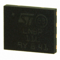
LNBP11LPUR STMicroelectronics, LNBP11LPUR Datasheet

LNBP11LPUR
Specifications of LNBP11LPUR
Available stocks
Related parts for LNBP11LPUR
LNBP11LPUR Summary of contents
Page 1
Features ■ Simplest integrated solution for LNB remote supply and control ■ 500 mA guaranteed output current ■ Dual input supply for reducing power dissipation (DFN package) ■ 3-state function to enable/disable and select the output voltage level through a ...
Page 2
Contents Contents 1 Diagram . . . . . . . . . . . . . . . . . . . . . . . . . . . . . . . . . . . . ...
Page 3
LNBP8L, LNBP9L, LNBP10L, LNBP11L 1 Diagram Figure 1. Block diagram VCC1 VCC1 VCC1 VCC1 VCC2 VCC2 VCC2 VCC2 TRISTATE ENABLE & TRISTATE ENABLE & TRISTATE ENABLE & TRISTATE ENABLE & EN/VSEL EN/VSEL EN/VSEL EN/VSEL VOUT SELECTION VOUT SELECTION VOUT SELECTION ...
Page 4
Pin configuration 2 Pin configuration Figure 2. Pin connections (top view for IPPAK, bottom view for DFN8) IPPAK Table 1. Pin description Pin n° Pin n° (DFN) (IPPAK) LNBP10/11L LNBP8/ (not available for ...
Page 5
LNBP8L, LNBP9L, LNBP10L, LNBP11L 3 Maximum ratings Table 2. Absolute maximum ratings Symbol VCC1, VCC2 Input voltages VCC1-OUTPUT VCC1 voltage with respect to OUTPUT voltage VCC2-OUTPUT VCC2 voltage with respect to OUTPUT voltage EN/VSEL, TEN, Logic input voltage LLC EXTM ...
Page 6
Electrical characteristics 4 Electrical characteristics Refer to the typical application circuits in ( EN/VSEL = LOW, TEN = LLC = LOW, EXTM = FLOATING, I CC2 ° °C, unless otherwise ...
Page 7
LNBP8L, LNBP9L, LNBP10L, LNBP11L Table 5. Electrical characteristics (continued) Symbol Parameter 3-state control pin input I ILT current LOW V Control input logic LOW IL V Control input logic HIGH IH I Control pins input current IH I Supply current ...
Page 8
Typical application circuits 5 Typical application circuits Figure 3. Single input supply voltage solution for IPPAK package versions 23V 23V 23V 23V 1N4001 1N4001 1N4001 1N4001 10µF 10µF ...
Page 9
LNBP8L, LNBP9L, LNBP10L, LNBP11L 6 Detailed description and application hints The LNBPxx is made up of several functional blocks (see below: 1. The oscillator is activated by setting the ENT pin (enable tone and is factory- trimmed at ...
Page 10
Detailed description and application hints time T ON has elapsed, the output goes low for a time of T power dissipated by the device low in overload conditions, and avoids the need for an oversized heat sink in this condition. ...
Page 11
LNBP8L, LNBP9L, LNBP10L, LNBP11L V line (see Figure CC1 voltage on the V CC1 For example, with I Equation 2 Where V is the forward voltage of the input diode D1 (see f Power dissipated in this resistor is: Equation ...
Page 12
Detailed description and application hints Figure 8. IPPAK mounted with a U-clip Note that the thickness of the IPPAK package (2.3 +/- 0.1 mm) is similar to that of the SOT- 32 and SOT-82 (2.55 +/- 0.15 mm). The same ...
Page 13
LNBP8L, LNBP9L, LNBP10L, LNBP11L 7 Typical performance characteristics Refer to the typical application circuit °C. J Figure 9. Output voltage vs. temperature 13.8 13.8 CC1 CC1 ...
Page 14
Typical performance characteristics Figure 15. Load regulation vs. temperature 250 250 CC1 CC1 200 200 CC2 CC2 from ...
Page 15
LNBP8L, LNBP9L, LNBP10L, LNBP11L Figure 21. Tone disable Figure 23. External modulation gain vs. frequency CC1 CC1 6.5 6 CC2 CC2 I ...
Page 16
Package mechanical data 8 Package mechanical data In order to meet environmental requirements, ST offers these devices in different grades of ® ECOPACK packages, depending on their level of environmental compliance. ECOPACK specifications, grade definitions and product status are available ...
Page 17
LNBP8L, LNBP9L, LNBP10L, LNBP11L Table 6. IPPAK mechanical data Dim Note: 1 Controlling dimensions: millimeter. 2 Burrs larger than 0.25 mm ...
Page 18
Package mechanical data Dim. Min 0.70 18/21 DFN8 (5x6 mm) mechanical data mm. Typ. Max. 0.90 1.00 0.02 0.05 0.20 0.40 0.47 ...
Page 19
... LNBP8L, LNBP9L, LNBP10L, LNBP11L 9 Ordering information Table 7. Order codes Part numbers LNBP8L LNBP9L LNBP10L LNBP11L Order codes DFN8 ( mm) LNBP8LIT LNBP9LIT LNBP10LPUR LNBP11LPUR Doc ID 15153 Rev 2 Ordering information Packing IPPAK Tape and reel Tape and reel Tape and reel Tape and reel 19/21 ...
Page 20
Revision history 10 Revision history Table 8. Document revision history Date Revision 11-Nov-2008 1 25-Aug-2010 2 20/21 Initial release. Document status promoted from preliminary data to datasheet. Doc ID 15153 Rev 2 LNBP8L, LNBP9L, LNBP10L, LNBP11L Changes ...
Page 21
... LNBP8L, LNBP9L, LNBP10L, LNBP11L Information in this document is provided solely in connection with ST products. STMicroelectronics NV and its subsidiaries (“ST”) reserve the right to make changes, corrections, modifications or improvements, to this document, and the products and services described herein at any time, without notice. All ST products are sold pursuant to ST’s terms and conditions of sale. ...


