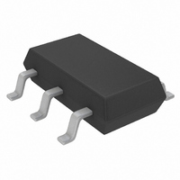
LT3467AES6#TRMPBF Linear Technology, LT3467AES6#TRMPBF Datasheet - Page 8

LT3467AES6#TRMPBF
Manufacturer Part Number
LT3467AES6#TRMPBF
Description
IC CONV DC/DC STEP-UP TSOT23-6
Manufacturer
Linear Technology
Type
Step-Up (Boost)r
Datasheet
1.LT3467AES6TRMPBF.pdf
(18 pages)
Specifications of LT3467AES6#TRMPBF
Internal Switch(s)
Yes
Synchronous Rectifier
No
Number Of Outputs
1
Voltage - Output
1.26 ~ 40 V
Current - Output
1.1A
Frequency - Switching
2.1MHz
Voltage - Input
2.4 ~ 16 V
Operating Temperature
-40°C ~ 85°C
Mounting Type
Surface Mount
Package / Case
TSOT-23-6, TSOT-6
Primary Input Voltage
16V
No. Of Outputs
1
Output Voltage
40V
Output Current
1.1A
No. Of Pins
6
Operating Temperature Range
-40°C To +85°C
Msl
MSL 1 - Unlimited
Rohs Compliant
Yes
Lead Free Status / RoHS Status
Lead free / RoHS Compliant
Power - Output
-
Other names
LT3467AES6#PBF
LT3467AES6#PBF
LT3467AES6#TRMPBF
LT3467AES6#TRMPBFTR
LT3467AES6#PBF
LT3467AES6#TRMPBF
LT3467AES6#TRMPBFTR
Available stocks
Company
Part Number
Manufacturer
Quantity
Price
APPLICATIONS INFORMATION
LT3467/LT3467A
Capacitor Selection
Low ESR (equivalent series resistance) capacitors should
be used at the output to minimize the output ripple voltage.
Multi-layer ceramic capacitors are an excellent choice,
as they have extremely low ESR and are available in very
small packages. X5R dielectrics are preferred, followed
by X7R, as these materials retain the capacitance over
wide voltage and temperature ranges. A 4.7μF to 15μF
output capacitor is suffi cient for most applications, but
systems with very low output currents may need only a
1μF or 2.2μF output capacitor. Solid tantalum or OS-CON
capacitors can be used, but they will occupy more board
area than a ceramic and will have a higher ESR. Always
use a capacitor with a suffi cient voltage rating.
Ceramic capacitors also make a good choice for the input
decoupling capacitor, which should be placed as close as
possible to the LT3467. A 1μF to 4.7μF input capacitor
is suffi cient for most applications. Table 2 shows a list
of several ceramic capacitor manufacturers. Consult the
manufacturers for detailed information on their entire
selection of ceramic parts.
Table 2. Ceramic Capacitor Manufacturers
Taiyo Yuden
AVX
Murata
The decision to use either low ESR (ceramic) capacitors
or the higher ESR (tantalum or OS-CON) capacitors can
affect the stability of the overall system. The ESR of any
capacitor, along with the capacitance itself, contributes
a zero to the system. For the tantalum and OS-CON ca-
pacitors, this zero is located at a lower frequency due to
the higher value of the ESR, while the zero of a ceramic
capacitor is at a much higher frequency and can generally
be ignored.
8
(408) 573-4150
(803) 448-9411
(714) 852-2001
www.t-yuden.com
www.avxcorp.com
www.murata.com
A phase lead zero can be intentionally introduced by placing
a capacitor (C4) in parallel with the resistor (R1) between
V
zero is determined by the following equation.
By choosing the appropriate values for the resistor and
capacitor, the zero frequency can be designed to improve
the phase margin of the overall converter. The typical
target value for the zero frequency is between 35kHz
to 55kHz. Figure 3 shows the transient response of the
step-up converter from Figure 8 without the phase lead
capacitor C4. Although adequate for many applications,
phase margin is not ideal as evidenced by 2-3 “bumps”
in both the output voltage and inductor current. A 22pF
capacitor for C4 results in ideal phase margin, which is
revealed in Figure 4 as a more damped response and less
overshoot.
Diode Selection
A Schottky diode is recommended for use with the LT3467
and the LT3467A. The Philips PMEG 2005 is a very good
choice. Where the switch voltage exceeds 20V, use the
PMEG 3005 (a 30V diode). Where the switch voltage
exceeds 30V, use the PMEG 4005 (a 40V diode). These
diodes are rated to handle an average forward current of
0.5A. In applications where the average forward current
of the diode exceeds 0.5A, a Philips PMEG 2010 rated at
1A is recommended. For higher effi ciency, use a diode
with better thermal characteristics such as the On Semi-
conductor MBRM120 (a 20V diode) or the MBRM140 (a
40V diode).
OUT
ƒ
Z
and V
=
2π • R1• C4
FB
as shown in Figure 2. The frequency of the
1
3467afe


