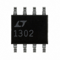
LT1302CS8#PBF Linear Technology, LT1302CS8#PBF Datasheet - Page 8

LT1302CS8#PBF
Manufacturer Part Number
LT1302CS8#PBF
Description
IC DC/DC CONV STEP-UP ADJ 8-SOIC
Manufacturer
Linear Technology
Type
Step-Up (Boost)r
Datasheet
1.LT1302CS8-5PBF.pdf
(16 pages)
Specifications of LT1302CS8#PBF
Internal Switch(s)
Yes
Synchronous Rectifier
No
Number Of Outputs
1
Voltage - Output
2 ~ 12 V
Current - Output
120mA
Frequency - Switching
220kHz
Voltage - Input
2 ~ 8 V
Operating Temperature
0°C ~ 70°C
Mounting Type
Surface Mount
Package / Case
8-SOIC (3.9mm Width)
Power - Output
700mW
Lead Free Status / RoHS Status
Lead free / RoHS Compliant
Available stocks
Company
Part Number
Manufacturer
Quantity
Price
APPLICATIONS
LT1302/LT1302-5
and there is no low frequency component. The total ESR
is under 0.03 . If a single 100 F aluminum electrolytic
capacitor is used instead, the converter mode-hops be-
tween current mode and Burst Mode due to high ESR,
causing the voltage comparator to trip as shown in Figure
5. The ripple voltage is now over 500mV
a low frequency component. Maximum allowable output
capacitor ESR can be calculated by the following formula:
where,
8
V
V
ESR
I
Figure 4. Low ESR Output Capacitor Results in Stable
Operation. Ripple Voltage is Under 30mV
I
Figure 5. Inexpensive Electrolytic Capacitor Has High
ESR, Resulting in Mode-Hop, Ripple Voltage Amplitude Is
Over 500mV
AC COUPLED
AC COUPLED
LOAD
LOAD
OS
REF
200mV/DIV
50mV/DIV
= 15mV
MAX
510mA
510mA
= 1.24V
10mA
10mA
V
V
OUT
OUT
P-P
V
V
OS
REF
and Includes Low Frequency Component
U
V
OUT
1
A
INFORMATION
U
500 s/DIV
500 s/DIV
W
P-P
P-P
and contains
1302 F04
1302 F05
U
Input Capacitor
The input supply should be decoupled with a good quality
electrolytic capacitor close to the LT1302 to provide a
stable input supply. Long leads or traces from power
source to the switcher can have considerable impedance
at the LT1302’s switching frequency. The input capacitor
provides a low impedance at high frequency. A 0.1 F
ceramic capacitor is required right at the V
input voltage can be above 5V, a 10 /1 F decoupling
network for V
This network is also recommended when driving a trans-
former.
Table 2 lists capacitor vendors along with device types.
Table 2. Recommended Capacitors
VENDOR
AVX
Sanyo
Sprague
Diode Selection
A 2A Schottky diode such as Motorola MBRS130LT3 has
been found to be the best available. Other choices include
1N5821 or MBRS130T3. Do not use “general purpose”
diodes such as 1N4001. They are much too slow for use
in switching regulator applications.
Figure 6. A 10 /1 F Decoupling Network at V
Recommended When Input Voltage Is Above 5V
V
IN
> 5V
SERIES
TPS
OS-CON
595D
IN
+
is recommended as detailed in Figure 6.
47 F
TO
100 F
+
TYPE
Surface Mount
Through Hole
Surface Mount
1 F
GND
V
IN
LT1302
10
PGND
SW
IN
PHONE NO.
(803) 448-9411
(619) 661-6835
(603) 224-1961
1302 F06
pin. When the
• • •
IN
Is


