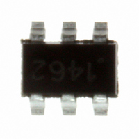
SC1462ISKTRT Semtech, SC1462ISKTRT Datasheet - Page 6

SC1462ISKTRT
Manufacturer Part Number
SC1462ISKTRT
Description
IC CHARGE PUMP DOUBLER SOT-23-6
Manufacturer
Semtech
Type
Switched Capacitor (Charge Pump), Doublerr
Datasheet
1.SC1462ISKTRT.pdf
(10 pages)
Specifications of SC1462ISKTRT
Internal Switch(s)
Yes
Synchronous Rectifier
No
Number Of Outputs
1
Voltage - Output
Adj to 12V
Current - Output
80mA
Frequency - Switching
160kHz
Voltage - Input
1.65 ~ 5.5 V
Operating Temperature
-40°C ~ 85°C
Mounting Type
Surface Mount
Package / Case
SOT-23-6
Lead Free Status / RoHS Status
Lead free / RoHS Compliant
Power - Output
-
Other names
SC1462ISKTR
Available stocks
Company
Part Number
Manufacturer
Quantity
Price
Part Number:
SC1462ISKTRT
Manufacturer:
SEMTECH/美国升特
Quantity:
20 000
Capacitor Selection
Capacitor selection is based on both the maximum ac-
ceptable ripple voltage and the maximum tolerable drop
at the output.
Ripple
The peak-to-peak output ripple voltage is dependent on
the following factors:
1) Oscillator frequency
2) ESR of C
3) Capacitance value of C
Item 1 is fi xed and depend on the charge pump device
used. Item 2, and 3 can be optimized for best perfor-
mance and reduction of the output ripple.
The following formula could be used for an approximation
for V
V
The voltage drop at the output is specifi ed with the follow-
ing equation:
R
1) Oscillator frequency
2) ESR of C
3) Capacitance value of C
4) Internal switch resistance (R
A good approximation for calculating the output
resistance is shown below.
POWER MANAGEMENT
Applications Information (Cont.)
© 2005 Semtech Corp.
OUT
OUT
R
OUT
resistances).
Drop
OUT_RIPPLE
is dependent on the following factors:
=
V
OUT_RIPPLE
f
OSC
.
OUT
OUT
× C
1
& C
BUCKET
=
V
OUT_DROP
BUCKET
2 × f
I
OSC
+ 2 × R
OUT
= I
× C
OUT
OUT
OUT
OUT
and C
× R
SW
+ 4 × ESR_ C
SW
+ 2 × I × ESR_ C
OUT
NOT RECOMMENDED FOR NEW DESIGN
= Total of all 4 switch
BUCKET
BUCKET
OUT
+ ESR_ C
OUT
6
This equation can be used to calculate C
cifi c V
for the R
Page 2 should be used in order to fi nd a worst-case num-
ber.
Layout Consideration
Standard power board layout should be followed to ensure
proper operation. Any stray inductance should be mini-
mized, this can be achieved by using large power planes
or traces, and reducing the distances between input, out-
put and the load. All components should be placed as
close as possible to the SC1462.
The following table shows typical capacitor characteris-
tics.
Component
0.1μF Ceramic 0603 Package
1.0μF Ceramic 1206 Package
10μF Ceramic 0603 Package
47μF Ceramic, 16V Tantalum D case
330μF, 6.3V “OSCON”
330μF, 16V AL. Electrolytic
820μF, 4V “OSCON”
1000μF, 10V Al. Electrolytic
OUT
when V
SW
from the Electrical Characteristics section on
IN
and I
OUT
are known. The maximum value
ESR(Ω)
0.050
0.040
0.075
0.100
0.025
0.143
0.012
0.053
www.semtech.com
BUCKET
SC1462
for a spe-
ESL(nH)
1.60
0.47
0.50
0.60
2.50
2.37
2.50
5.00


