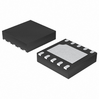
SC194BMLTRT Semtech, SC194BMLTRT Datasheet - Page 8

SC194BMLTRT
Manufacturer Part Number
SC194BMLTRT
Description
IC SYNC BUCK CONV 1A 10-MLP
Manufacturer
Semtech
Type
Step-Down (Buck)r
Datasheet
1.SC194BMLTRT.pdf
(17 pages)
Specifications of SC194BMLTRT
Internal Switch(s)
Yes
Synchronous Rectifier
No
Number Of Outputs
1
Voltage - Output
Adjustable
Current - Output
1A
Frequency - Switching
1MHz
Voltage - Input
2.7 ~ 5.5 V
Operating Temperature
-40°C ~ 85°C
Mounting Type
Surface Mount
Package / Case
10-MLP
Lead Free Status / RoHS Status
Lead free / RoHS Compliant
Power - Output
-
Other names
SC194BMLTR
Available stocks
Company
Part Number
Manufacturer
Quantity
Price
Part Number:
SC194BMLTRT
Manufacturer:
SEMTECH/美国升特
Quantity:
20 000
In PSAVE mode V
upper level by a switching burst. Once the upper level has
been reached the switching is stopped and the quiescent
current is reduced. V
in this low current state as the load current discharges
the output capacitor. The burst-to-off period in PSAVE will
decrease as the load current reduces.
The PSAVE switching burst frequency is controlled so
that the inductor current ripple is similar to that in PWM
mode.
The SC194B automatically detects when to exit PSAVE
mode by monitoring V
mode, the load must be increased, causing V
decrease until the power save exit threshold is reached.
PSAVE levels are set high to minimize the undershoot
when exiting PSAVE. The lower PSAVE comparator level
is set +0.7% above V
at +1.5% above V
V
If PSAVE operation is required then a 22μF output
capacitor must be used.
© 2006 Semtech Corp.
0.7%
POWER MANAGEMENT
Applications Information (Cont.)
1.5%
V
-2%
0 A
OUT
OUT
.
BURST
PSAVE Mode at Light Load
Inductor Current
OFF
Power Save Operation
OUT
OUT
, with the exit threshold at -2% below
OUT
OUT
is driven from a lower level to an
OUT
falls from the upper to lower levels
, and the upper comparator level
. For the SC194B to exit PSAVE
Higher Load
Applied
Time
PWM Mode at Medium/
High Load
OUT
to
8
100% Duty Cycle Operation
The 100% duty cycle mode may be selected by connecting
the MODE pin high. This will allow the SC194B to maintain
output regulation under low input voltage/high output
voltage conditions.
In 100% duty cycle operation, as the input supply drops
toward the output voltage, the PMOS on-time increases
linearly above the maximum value in fi xed-frequency
operation until the PMOS is active continuously. Once
the PMOS is switched on continuously, the output voltage
tracks the input voltage minus the voltage drop across
the PMOS power device and inductor according to the
following relationship:
where,
Inductor Selection
The SC194B is designed for use with a 4.7μH inductor.
The magnitude of the inductor current ripple is dependent
on the inductor value and can be determined by the
following equation:
This equation demonstrates the relationship between
input voltage, output voltage, and inductor ripple
current.
The inductor should have a low DCR to minimize the
conduction losses and maximize effi ciency.
minimum requirement, the DC current rating of the
inductor should be equal to the maximum load current
plus half of the inductor current ripple as shown by the
following equation:
V
V
I
R
R
OUT
OUT
IN
DSP
IND
V
V
= Output voltage
= Input voltage
= Output current
= PMOS switch ON resistance
= Series resistance of the inductor
I
OUT
OUT
L
I
L(PK)
L
V
V
V
IN
IN
OUT
f
osc
I
O
I
I
UT(MAX)
OUT
OUT
1
(R
(R
V
DSP
DSP
2
V
OUT
I
IN
L
R
R
IND
IND
)
)
www.semtech.com
SC194B
As a


