L4964HT STMicroelectronics, L4964HT Datasheet
L4964HT
Specifications of L4964HT
L4964HT
Available stocks


Related parts for L4964HT


L4964HT Summary of contents
Page 1
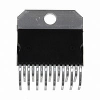
... PIN CONNECTION (top view) July 2003 HIGH CURRENT SWITCHING REGULATOR L4964 MULTIWATT15 Vertical (Plastic Package) ORDERING NUMBER : L4964 MULTIWATT15 Horizontal (Plastic Package) ORDERING NUMBER : L4964HT Pins must not be connected. Leave open circuit. 1/13 ...
Page 2
L4964 PIN FUNCTIONS N Name 1 N.C. Must not be connected. Leave open circuit. 2 Output Regulator Output. 3 Supply Voltage Unregulated Voltage Input. An internal regulator powers the L4964’s internal logic. 4 N.C. Must not be connected. Leave open ...
Page 3
CIRCUIT OPERATION (refer to the block diagram) The L4964 is a monolithic stepdown switching regu- lator providing output voltages from 5 and delivering 4A. The regulation loop consists of a sawtooth oscillator, error amplifier, comparator and ...
Page 4
L4964 Figure 2 : Soft Start Waveforms Figure 3 : Current Limiter Waveforms ABSOLUTE MAXIMUM RATINGS Symbol V Input Voltage (pin – V Input to Output Voltage Difference Output DC Voltage 2 Output Peak ...
Page 5
ELECTRICAL CHARACTERISTICS (refer to the test circuits Symbol Parameter DYNAMIC CHARACTERISTICS (pin 6 to GND unless otherwise specified) V Output Voltage Range o V Input Voltage Range i V Line Regulation o V Load Regulation o ...
Page 6
L4964 ELECTRICAL CHARACTERISTICS (continued) (refer to the test circuits Symbol Parameter ERROR AMPLIFIER (continued) I Input Bias Current Open Loop Gain v OSCILLATOR AND PWM COMPARATOR –I Input Bias Current of 7 PWM ...
Page 7
Figure 5 : PC. Board and Component Layout of the Circuit of Fig. 4 (1:1 scale) L4964 7/13 ...
Page 8
L4964 Figure Test Circuits. Figure 6a. Figure 6c Set V FOR Change V to obtain ...
Page 9
Figure 7 : Switching Frequency vs. R1 (see fig. 4). Figure 9 : Reference Voltage (pin 10) vs. Junc- tion Temperature (see fig. 4). Figure 11 : Efficiency vs. Output Voltage. Figure 8 : Open Loop Frequency and Phase Res- ...
Page 10
L4964 APPLICATION INFORMATION CHOOSING THE INDUCTOR AND CAPACITOR The input and output capacitors of the L4964 must have a low ESR and low inductance at high current ripple. Preferably, the inductor should be a toroidal type or wound on a ...
Page 11
DIM. MIN. TYP. MAX. MIN 2.65 C 1.6 E 0.49 0.55 0.019 F 0.66 0.75 0.026 G 1.02 1.27 1.52 0.040 G1 17.53 17.78 18.03 0.690 H1 19.6 20.2 0.772 H2 19.6 20.2 0.772 L1 17.8 ...
Page 12
L4964 mm DIM. MIN. TYP. MAX 2. 0.49 0.55 0.019 F 0.66 0.75 0.026 G 1.02 1.27 1.52 0.040 G1 17.53 17.78 18.03 0.690 H1 19.6 0.772 H2 20.2 L 21.9 22.2 ...
Page 13
... No license is granted by implication or otherwise under any patent or patent rights of STMicroelectronics. Specification mentioned in this publication are subject to change without notice. This publication supersedes and replaces all information previously supplied. STMi- croelectronics products are not authorized for use as critical components in life support devices or systems without express written approval of STMicroelectronics ...