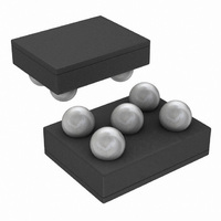
LM3673TL-1.5/NOPB National Semiconductor, LM3673TL-1.5/NOPB Datasheet - Page 15

LM3673TL-1.5/NOPB
Manufacturer Part Number
LM3673TL-1.5/NOPB
Description
IC CONV DC/DC 350MA 1.5V 5MICRO
Manufacturer
National Semiconductor
Series
PowerWise®r
Type
Step-Down (Buck)r
Datasheet
1.LM3673TL-1.5NOPB.pdf
(20 pages)
Specifications of LM3673TL-1.5/NOPB
Internal Switch(s)
Yes
Synchronous Rectifier
Yes
Number Of Outputs
1
Voltage - Output
1.5V
Current - Output
350mA
Frequency - Switching
2MHz
Voltage - Input
2.7 ~ 5.5 V
Operating Temperature
-30°C ~ 85°C
Mounting Type
Surface Mount
Package / Case
5-MicroSMD
Power - Output
1.18W
For Use With
LM3673TL-1.5EV - BOARD EVALUATION LM3673TL-1.5
Lead Free Status / RoHS Status
Lead free / RoHS Compliant
Other names
LM3673TL-1.5TR
Available stocks
Company
Part Number
Manufacturer
Quantity
Price
4.7 µF for C
10 µF for C
OUTPUT CAPACITOR SELECTION
A ceramic output capacitor of 10 µF, 6.3V is sufficient for most
applications. Use X7R or X5R types; do not use Y5V. DC bias
characteristics of ceramic capacitors must be considered
when selecting case sizes like 0805 and 0603. DC bias char-
acteristics vary from manufacturer to manufacturer and dc
bias curves should be requested from them as part of the ca-
pacitor selection process.
The minimum output capacitance to guarantee good per-
formance is 5.75µF at 1.8V dc bias including tolerances
and over ambient temperature range. The output filter ca-
pacitor smoothes out current flow from the inductor to the
load, helps maintain a steady output voltage during transient
load changes and reduces output voltage ripple. These ca-
pacitors must be selected with sufficient capacitance and
sufficiently low ESR to perform these functions.
The output voltage ripple is caused by the charging and dis-
charging of the output capacitor and by the R
calculated as:
Voltage peak-to-peak ripple due to capacitance can be ex-
pressed as follow:
GRM21BR60J475K
GRM21BR60J106K
C2012X5R0J475K
C1608X5R0J475K
C2012X5R0J106K
C1608X5R0J106K
JMK212BJ475K
JMK212BJ106K
KSLI-2520101AG2R2 *
LQM2HPN2R2MJ0
LQM31PN2R2M00
TABLE 1. Suggested Inductors and Their Suppliers
LPO3310-222MX
BRL2518T2R2M
CDRH2D14-2R2
Model
DO3314-222MX
OUT
IN
Model
Ceramic, X5R
Ceramic, X5R
Ceramic, X5R
Ceramic, X5R
Ceramic, X5R
Ceramic, X5R
Ceramic, X5R
Ceramic, X5R
TABLE 2. Suggested Capacitors and Their Suppliers
Type
Hitachi Metals
Taiyo Yuden
ESR
Coilcraft
Coilcraft
Vendor
Sumida
Murata
Murata
and can be
Taiyo-Yuden
Taiyo-Yuden
Vendor
Murata
Murata
Chip
TDK
TDK
TDK
TDK
Coil
15
(* mass production in Feb. 2007; Contact vendor for further information)
Voltage peak-to-peak ripple due to ESR can be expressed as
follow:
V
Because these two components are out of phase the rms (root
mean squared) value can be used to get an approximate val-
ue of peak-to-peak ripple.
The peak-to-peak ripple voltage, rms value can be expressed
as follow:
Note that the output voltage ripple is dependent on the induc-
tor current ripple and the equivalent series resistance of the
output capacitor (R
The R
dependent); make sure the value used for calculations is at
the switching frequency of the part.
PP-ESR
Dimensions LxWxH(mm)
ESR
= (2 * I
3.2 x 3.2 x 1.55
3.2 x 1.6 x 0.95
2.5 x 1.8 x 1.2
3.3 x 3.3 x 1.4
3.3 x 3.3 x 1.0
2.5 x 2.0 x 1.0
2.5 x 2.0 x 1.2
is frequency dependent (as well as temperature
Voltage Rating
RIPPLE
ESR
6.3V
6.3V
6.3V
6.3V
6.3V
6.3V
6.3V
6.3V
) * R
).
ESR
0805 (2012)
0805 (2012)
0805 (2012)
0603 (1608)
0805 (2012)
0805 (2012)
0805 (2012)
0603 (1608)
Inch (mm)
Case Size
D.C.R (max)
135 mΩ
200 mΩ
150 mΩ
115 mΩ
220 mΩ
160 mΩ
94 mΩ
www.national.com


