LM2745MTC/NOPB National Semiconductor, LM2745MTC/NOPB Datasheet
LM2745MTC/NOPB
Specifications of LM2745MTC/NOPB
*LM2745MTC/NOPB
LM2745MTC


Related parts for LM2745MTC/NOPB

LM2745MTC/NOPB Summary of contents
Page 1
... In addition, the shutdown pin of the IC can be used for providing startup delay, and the soft-start pin can be used for implementing precise tracking, for the purpose of sequencing with respect to an external rail. Typical Application © 2009 National Semiconductor Corporation Features ■ Switching frequency from 50 kHz to 1 MHz ■ ...
Page 2
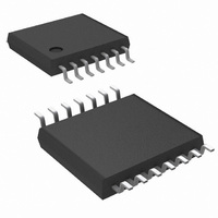
Connection Diagrams 14-Lead Plastic TSSOP θ = 155°C Package Number MTC14 Ordering Information Order Number Package Type LM2745MTC LM2745MTCX TSSOP-14 LM2748MTC LM2748MTCX Pin Descriptions BOOT (Pin 1) - Bootstrap pin. This is the supply rail for the high-side ...
Page 3
... Absolute Maximum Ratings If Military/Aerospace specified devices are required, please contact the National Semiconductor Sales Office/ Distributors for availability and specifications BOOT Voltage I SEN FREQ/SYNC Voltage All other pins Junction Temperature Storage Temperature Soldering Information Electrical Characteristics V = 3.3V unless otherwise indicated. Typicals and limits appearing in plain type apply for T CC boldface type apply over full Operating Temperature Range ...
Page 4
Symbol Parameter GATE DRIVE I BOOT Pin Quiescent Current Q-BOOT R High-Side MOSFET Driver Pull-Up HG_UP ON resistance R High-Side MOSFET Driver Pull- HG_DN Down ON resistance R Low-Side MOSFET Driver Pull-Up LG_UP ON resistance R Low-Side MOSFET Driver Pull- ...
Page 5
Typical Performance Characteristics Efficiency (V = 1.2V) OUT V = 3.3V MHz CC SW Frequency vs Temperature Switch Waveforms V = 3.3V 5V OUT nF, f ...
Page 6
Start-Up (No-Load 3. Load Transient Response V = 3.3V 14V MHz SW Frequency vs. Frequency Adjust Resistor ...
Page 7
Maximum Duty Cycle 600 kHz SW 20137493 Maximum Duty Cycle MHz 20137494 www.national.com ...
Page 8
Block Diagram Application Information The LM2745 voltage-mode, high-speed synchronous buck regulator with a PWM control scheme designed for use in set-top boxes, thin clients, DSL/Cable modems, and other applications that require high efficiency buck convert- ers. ...
Page 9
ADJUST RESISTOR in the Typical Performance Character- istics section. When it is desired to synchronize the switching frequency with an external clock source, the LM2745 has the unique ability to synchronize from this external source within the range of 250 ...
Page 10
One way to use the tracking feature is to design the tracking resistor divider so that the master supply’s output voltage (V ) and the LM2745/8’s output voltage (represented sym- OUT1 bolically in Figure i.e. without ...
Page 11
For example, if the master supply output voltage slew rate was 1V/ms and the desired delay time between the startup of the master supply and LM2745/8 output voltage was 5 ms, then the desired SD pin slew rate would be ...
Page 12
So far, in the discussion above, the forward drop across the bootstrap diode has been ignored. But since that does affect the output of the driver somewhat good idea to include this drop in the following examples. ...
Page 13
POWER GOOD SIGNAL The open drain output on the Power Good pin needs a pull- up resistor to a low voltage source. The pull-up resistor should be chosen so that the current going into the Power Good pin is less ...
Page 14
SHUTDOWN If the shutdown pin is pulled low, (below 0.8V) the LM2745/8 enters shutdown mode, and discharges the soft-start capac- itor through a MOSFET switch. The high ...
Page 15
In this example, in order to maintain a 2% peak-to-peak output voltage ripple and a 40% peak-to-peak inductor current ripple, the required maximum ESR is 20 mΩ. The Sanyo 4SP560M electrolytic capacitor will give an equivalent ESR of 14 mΩ. ...
Page 16
FIGURE 13. Power Stage and Error Amp One popular method for selecting the compensation compo- nents is to create Bode plots of gain and phase for the power stage and error amplifier. Combined, they make the overall bandwidth and phase ...
Page 17
In most voltage mode compensation schemes, including Type III, a single pole is placed at the origin to boost DC gain as high as possible. Two zeroes f and f Z1 double pole frequency to cancel the double pole phase ...
Page 18
In practice, a good trade off between phase margin and band- width can be obtained by selecting the closest ±10% capac- itor values above what are suggested for C closest ±10% capacitor value below the suggestion for C and the ...
Page 19
The FDS6898A has a typical turn-on rise time t fall time and 16 ns, respectively. The switching f losses for this type of dual N-Channel MOSFETs are 0.061W. FET Conduction Loss (P ) CND P = ...
Page 20
Example Circuits PART PART NUMBER U1 LM2745 Q1 FDS6898A D1 MBR0520LTI L1 DO3316P-472 C 1 16SP100M 6SP220M VJ1206Y104KXXA CC BOOT VJ0805Y332KXXA C3 C VJ0805A123KXAA SS C ...
Page 21
PART PART NUMBER U1 LM2745 Q1 FDS6898A D1 MBR0520LTI L1 DO3316P-682 C 1 16SP100M 10SP56M VJ1206Y104KXXA CC BOOT VJ0805Y182KXXA C3 C VJ0805A123KXAA SS C VJ0805A821KXAA C2 ...
Page 22
PART PART NUMBER U1 LM2745 Q1 FDS6898A D1 MBR0520LTI L1 DO3316P-332 C 1 16SP100M 6SP220M VJ1206Y104KXXA CC BOOT VJ0805Y222KXXA C3 C VJ0805A123KXAA SS C VJ0805Y332KXXA C2 ...
Page 23
Physical Dimensions inches (millimeters) unless otherwise noted TSSOP-14 Pin Package NS Package Number MTC14 23 www.national.com ...
Page 24
... For more National Semiconductor product information and proven design tools, visit the following Web sites at: Products Amplifiers www.national.com/amplifiers Audio www.national.com/audio Clock and Timing www.national.com/timing Data Converters www.national.com/adc Interface www.national.com/interface LVDS www.national.com/lvds Power Management www.national.com/power Switching Regulators www.national.com/switchers LDOs www.national.com/ldo LED Lighting www ...