LM2575HVT-15/NOPB National Semiconductor, LM2575HVT-15/NOPB Datasheet
LM2575HVT-15/NOPB
Specifications of LM2575HVT-15/NOPB
*LM2575HVT-15/NOPB
LM2575HVT-15
Available stocks


Related parts for LM2575HVT-15/NOPB


LM2575HVT-15/NOPB Summary of contents
Page 1
... Typical Application (Fixed Output Voltage Versions) Note: Pin numbers are for the TO-220 package. SIMPLE SWITCHER ® registered trademark of National Semiconductor Corporation © 2007 National Semiconductor Corporation ® 1A Step-Down Voltage Regulator Features ■ 3.3V, 5V, 12V, 15V, and adjustable output versions ■ ...
Page 2
Block Diagram and Typical Application 3.3V 1.7k 5V 3.1k 12V 8.84k 15V 11.3k For ADJ. Version R1 = Open 0Ω Note: Pin numbers are for the TO-220 package. www.national.com FIGURE ...
Page 3
... Internal Connection LM2575M-XX or LM2575HVM-XX See NS Package Number M24B TO-263(S) 5-Lead Surface-Mount Package 1147529 Top View 1147530 Side View LM2575S-XX or LM2575HVS-XX See NS Package Number TS5B 3 1147524 Side View LM2575T-XX Flow LB03 or LM2575HVT-XX Flow LB03 See NS Package Number T05D 1147526 Top View www.national.com ...
Page 4
... LM2575HVT-5.0 LM2575T-12 LM2575HVT-12 LM2575T-15 LM2575HVT-15 LM2575T-ADJ LM2575HVT-ADJ LM2575T-3.3 Flow LB03 LM2575HVT-3.3 Flow LB03 LM2575T-5.0 Flow LB03 LM2575HVT-5.0 Flow LB03 LM2575T-12 Flow LB03 LM2575HVT-12 Flow LB03 LM2575T-15 Flow LB03 LM2575HVT-15 Flow LB03 LM2575T-ADJ Flow LB03 LM2575HVT-ADJ Flow LB03 LM2575N-5.0 LM2575HVN-5.0 LM2575N-12 LM2575HVN-12 ...
Page 5
... Absolute Maximum Ratings If Military/Aerospace specified devices are required, please contact the National Semiconductor Sales Office/ Distributors for availability and specifications. Maximum Supply Voltage LM1575/LM2575 LM2575HV ON /OFF Pin Input Voltage Output Voltage to Ground (Steady State) Power Dissipation Storage Temperature Range Maximum Junction Temperature LM1575-3 ...
Page 6
Symbol Parameter V Output Voltage 0.2A OUT LM2575HV 8V Circuit of Figure 2 η Efficiency V LM1575-12, LM2575-12, LM2575HV-12 Electrical Characteristics Specifications with standard type face are for T Range . Symbol Parameter SYSTEM PARAMETERS (Note 4) Test Circuit Figure ...
Page 7
LM1575-ADJ, LM2575-ADJ, LM2575HV-ADJ Electrical Characteristics Specifications with standard type face are for T Range. Symbol Parameter SYSTEM PARAMETERS (Note 4) Test Circuit Figure 2 V Feedback Voltage V OUT IN V OUT Circuit of Figure 2 V Feedback Voltage 0.2A ...
Page 8
Symbol Parameter θ Thermal Resistance T Package, Junction to Ambient (Note 9) JA θ T Package, Junction to Ambient (Note 10) JA θ T Package, Junction to Case JC θ N Package, Junction to Ambient (Note 11) JA θ M ...
Page 9
Typical Performance Characteristics Normalized Output Voltage Dropout Voltage Quiescent Current (Circuit of Figure 2) 1147532 1147534 1147536 9 Line Regulation 1147533 Current Limit 1147535 Standby Quiescent Current 1147537 www.national.com ...
Page 10
Oscillator Frequency Efficiency Quiescent Current vs Duty Cycle www.national.com 1147538 Minimum Operating Voltage 1147540 1147542 10 Switch Saturation Voltage 1147539 1147541 Feedback Voltage vs Duty Cycle 1147543 ...
Page 11
Feedback Pin Current Switching Waveforms OUT A: Output Pin Voltage, 10V/div B: Output Pin Current, 1A/div C: Inductor Current, 0.5A/div D: Output Ripple Voltage, 20 mV/div, AC-Coupled Horizontal Time Base: 5 μs/div Maximum Power Dissipation (TO-263) (See ...
Page 12
Test Circuit and Layout Guidelines As in any switching regulator, layout is very important. Rapidly switching currents associated with wiring inductance gener- ate voltage transients which can cause problems. For minimal inductance and ground loops, the length of the leads ...
Page 13
LM2575 Series Buck Regulator Design Procedure PROCEDURE (Fixed Output Voltage Versions) Given Regulated Output Voltage (3.3V, 5V, 12V, or 15V) OUT V (Max) = Maximum Input Voltage IN I (Max) = Maximum Load Current LOAD 1. Inductor Selection ...
Page 14
Inductor Value Selection Guides (For Continuous Mode Operation) FIGURE 3. LM2575(HV)-3.3 FIGURE 4. LM2575(HV)-5.0 www.national.com 1147510 FIGURE 5. LM2575(HV)-12 1147511 FIGURE 6. LM2575(HV)-15 1147514 FIGURE 7. LM2575(HV)-ADJ 14 1147512 1147513 ...
Page 15
PROCEDURE (Adjustable Output Voltage Versions) Given Regulated Output Voltage OUT V (Max) = Maximum Input Voltage IN I (Max) = Maximum Load Current LOAD F = Switching Frequency (Fixed at 52 kHz) 1. Programming Output Voltage (Selecting R1 ...
Page 16
... An aluminum or tantalum electrolytic bypass capacitor located close to the regulator is needed for stable operation. To further simplify the buck regulator design procedure, National Semiconductor is making available computer design software to be used with the Simple Switcher line of switching regulators. Switchers Made Simple (version 3.3) is available on a (3½ ) diskette for IBM compatible computers from a National Semiconductor sales office in your area ...
Page 17
V R 20V 1N5817 MBR120P SR102 30V 1N5818 MBR130P 11DQ03 SR103 40V 1N5819 MBR140P 11DQ04 SR104 50V MBR150 11DQ05 SR105 60V MBR160 11DQ06 SR106 Inductor Inductor Code Value L100 L150 L220 L330 L470 L680 H150 H220 H330 H470 H680 H1000 ...
Page 18
Application Hints INPUT CAPACITOR ( maintain stability, the regulator input pin must be bypassed with at least a 47 μF electrolytic capacitor. The capacitor's leads must be kept short, and located near the regulator. If the operating ...
Page 19
The capacitor's ripple current rating at 52 kHz should be at least 50% higher than the peak-to-peak inductor ripple cur- ...
Page 20
SO package, and 30°C/W for the N package can be realized with a carefully engineered pc board. Included on the Switchers Made Simple design software is a more precise (non-linear) thermal model ...
Page 21
NEGATIVE BOOST REGULATOR Another variation on the buck-boost topology is the negative boost configuration. The circuit in Figure 11 accepts an input voltage ranging from −5V to −12V and provides a regulated −12V output. Input voltages greater than −12V will ...
Page 22
Note: Pin numbers are for the TO-220 package. FIGURE 15. 1.2V to 55V Adjustable 1A Power Supply with Low Output Ripple www.national.com 22 1147520 ...
Page 23
Definition of Terms BUCK REGULATOR A switching regulator topology in which a higher voltage is converted to a lower voltage. Also known as a step-down switching regulator. BUCK-BOOST REGULATOR A switching regulator topology in which a positive voltage is converted ...
Page 24
Physical Dimensions LM1575J-12/883, LM1575J-15/883, or LM1575J-ADJ/883 Order Number LM2575M-5.0, LM2575HVM-5.0, LM2575M-12, www.national.com inches (millimeters) unless otherwise noted 16-Lead Ceramic Dual-in-Line (J) Order Number LM1575J-3.3/883, LM1575J-5.0/883, NS Package Number J16A 24-Lead Wide Surface Mount (WM) LM2575HVM-12, LM2575M-15, LM2575HVM-15, LM2575M-ADJ or LM2575HVM-ADJ ...
Page 25
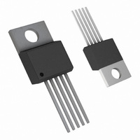
... Molded DIP (N) Order Number LM2575N-5.0, LM2575HVN-5.0, LM2575N-12, LM2575HVN-12, LM2575N-15, LM2575HVN-15, LM2575N-ADJ or LM2575HVN-ADJ NS Package Number N16A 5-Lead TO-220 (T) Order Number LM2575T-3.3, LM2575HVT-3.3, LM2575T-5.0, LM2575HVT-5.0, LM2575T-12, LM2575HVT-12, LM2575T-15, LM2575HVT-15, LM2575T-ADJ or LM2575HVT-ADJ NS Package Number T05A 25 www.national.com ...
Page 26
Order Number LM2575S-3.3, LM2575HVS-3.3, LM2575S-5.0, LM2575HVS-5.0, LM2575S-12, LM2575HVS-12, LM2575S-15, LM2575HVS-15, LM2575S-ADJ or LM2575HVS-ADJ www.national.com TO-263, Molded, 5-Lead Surface Mount NS Package Number TS5B 26 ...
Page 27
... Bent, Staggered 5-Lead TO-220 (T) Order Number LM2575T-3.3 Flow LB03, LM2575HVT-3.3 Flow LB03, LM2575T-5.0 Flow LB03, LM2575HVT-5.0 Flow LB03, LM2575T-12 Flow LB03, LM2575HVT-12 Flow LB03, LM2575T-15 Flow LB03, LM2575HVT-15 Flow LB03, LM2575T-ADJ Flow LB03 or LM2575HVT-ADJ Flow LB03 NS Package Number T05D 27 www.national.com ...
Page 28
... National Semiconductor and the National Semiconductor logo are registered trademarks of National Semiconductor Corporation. All other brand or product names may be trademarks or registered trademarks of their respective holders. ...