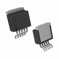
LM2577S-12/NOPB National Semiconductor, LM2577S-12/NOPB Datasheet - Page 16

LM2577S-12/NOPB
Manufacturer Part Number
LM2577S-12/NOPB
Description
IC REG SIMPLE SWITCHER TO-263-5
Manufacturer
National Semiconductor
Series
SIMPLE SWITCHER®r
Type
Step-Up (Boost), Flyback, Forward Converterr
Datasheet
1.LM2577T-15NOPB.pdf
(31 pages)
Specifications of LM2577S-12/NOPB
Internal Switch(s)
Yes
Synchronous Rectifier
No
Number Of Outputs
1
Voltage - Output
12V
Current - Output
3A
Frequency - Switching
52kHz
Voltage - Input
3.5 ~ 40 V
Operating Temperature
-40°C ~ 125°C
Mounting Type
Surface Mount
Package / Case
D²Pak, TO-263 (5 leads + tab)
Input Voltage
40V
Output Voltage
15V
No. Of Pins
5
Operating Temperature Range
-40°C To +125°C
Msl
MSL 3 - 168 Hours
Switching Frequency Max
52kHz
Termination Type
SMD
Voltage Regulator Type
Boost Switching
Rohs Compliant
Yes
Filter Terminals
SMD
Input Voltage Primary Max
40V
Output Current Max
3A
For Use With
551011367-061 - BOARD WEBENCH LM2577,LM2585/87
Lead Free Status / RoHS Status
Lead free / RoHS Compliant
Power - Output
-
Other names
*LM2577S-12
*LM2577S-12/NOPB
LM2577S-12
*LM2577S-12/NOPB
LM2577S-12
www.national.com
Application Hints
where V
recovery diodes (typically);
E • T, the product of volts x time that charges the inductor:
I
B. Identify Inductor Value:
If L
on to step C. Otherwise, the inductor value found in step B1
is too low; an appropriate inductor code should be obtained
from the graph as follows:
IND,DC
ditions for which the LM1577/LM2577 output switch
would be operating beyond its switch current rating. The
minimum operating voltage for the LM1577/LM2577 is
3.5V.
From here, proceed to step C.
2. For Adjustable version
Preliminary calculations:
The inductor selection is based on the calculation of the
following three parameters:
D
MIN
1. From Figure 9, identify the inductor code for the
region indicated by the intersection of E • T and I
This code gives the inductor value in microhenries. The
L or H prefix signifies whether the inductor is rated for a
maximum E • T of 90 V • µs (L) or 250 V • µs (H).
2. If D
the minimum inductance needed to ensure the switching
regulator’s stability:
(max)
, the average inductor current under full load;
is smaller than the inductor value found in step B1, go
F
, the maximum switch duty cycle (0 ≤ D ≤ 0.9):
<
= 0.5V for Schottky diodes and 0.8V for fast
0.85, go on to step C. If D ≥ 0.85, then calculate
(Continued)
IND,DC
.
16
1. Find the lowest value inductor that is greater than L
2. Find where E • T intersects this inductor value to determine
if it has an L or H prefix. If E • T intersects both the L and H
regions, select the inductor with an H prefix.
FIGURE 7. LM2577-12 Inductor Selection Guide
FIGURE 8. LM2577-15 Inductor Selection Guide
01146828
01146827
MIN
.


