LM3676SD-ADJ/NOPB National Semiconductor, LM3676SD-ADJ/NOPB Datasheet
LM3676SD-ADJ/NOPB
Specifications of LM3676SD-ADJ/NOPB


Related parts for LM3676SD-ADJ/NOPB


LM3676SD-ADJ/NOPB Summary of contents
Page 1
... The LM3676 is available in a 8-lead non-pullback LLP pack- age in leaded (PB) and lead-free (NO PB) versions. A high switching frequency of 2 MHz (typ) allows use of tiny surface- mount components, an inductor and two ceramic capacitors. Typical Application Circuits © 2007 National Semiconductor Corporation Features ■ 16 µA typical quiescent current ■ ...
Page 2
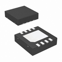
Connection Diagram and Package Mark Information Pin Descriptions (8-Lead LLP) Pin # Name 1 PGND MODE SGND 8 VIN www.national.com FIGURE 2. Typical Application Circuit for ADJ version FIGURE 3. ...
Page 3
... Ordering Information (8-Lead LLP) Voltage Order Number Option ADJ LM3676SD-ADJ LM3676SDX-ADJ LM3676SD-ADJ LM3676SDX-ADJ 1.5 LM3676SD-1.5 LM3676SDX-1.5 LM3676SD-1.5 LM3676SDX-1.5 1.8 LM3676SD-1.8 LM3676SDX-1.8 LM3676SD-1.8 LM3676SDX-1.8 3.3 LM3676SD-3.3 LM3676SDX-3.3 LM3676SD-3.3 LM3676SDX-3.3 Spec Package Marking NOPB NOPB S008B NOPB NOPB S007B NOPB NOPB S009B NOPB ...
Page 4
... Junction Temperature (T ) J-MAX Storage Temperature Range Maximum Lead Temperature (Soldering, 10 sec.) ESD Rating (Note 4) Electrical Characteristics apply over the full operating junction temperature range (−30°C the LM3676SD with V = 3.6V IN Symbol Parameter V Feedback Voltage (Fixed / Adj) (Note 11) FB Line Regulation Load Regulation ...
Page 5
Note 10: ADJ version is configured to 1.5V output. Note 11: Test condition: for V less than 2.5V, V OUT Dissipation Rating Table θ JA 56°C/W (4 layer board) 8 Lead non- pullback LLP package = 3.6V; for V greater ...
Page 6
Block Diagram www.national.com FIGURE 4. Simplified Functional Diagram 6 20176418 ...
Page 7
... Typical Performance Characteristics Circuit of LM3676SD 3.6V 1.5V OUT Quiescent Supply Current vs. Supply Voltage Feedback Bias Current vs. Temp R vs. Temperature DS(ON) = 25°C, unless otherwise noted. A Shutdown Current vs. Temp 20176404 Switching Frequency vs. Temperature 20176440 Open/Closed Loop Current Limit vs. Temperature 20176433 7 20176405 20176447 20176448 ...
Page 8
Output Voltage vs. Supply Voltage (V = 1.5V) OUT Output Voltage vs. Output Current (V = 1.5V) OUT Efficiency vs. Output Current (V = 1.5V 2.2 µH) OUT www.national.com Output Voltage vs. Temperature 20176429 Line Transient Response V ...
Page 9
Load Transient Response (V = 1.5V) OUT (PFM Mode 0.5mA to 50mA) Mode Change by Load Transients V = 1.5V (PFM to PWM) OUT Mode Change by Mode Pin V = 1.5V (PFM to PWM) OUT Load Transient Response (V ...
Page 10
Load Transient Response V = 1.5V (PWM Mode) OUT Start Up into PFM Mode V = 1.5V (Output Current= 1mA) OUT www.national.com Start Up into PWM Mode V = 1.5V (Output Current= 300mA) OUT 20176413 20176419 10 20176424 ...
Page 11
Operation Description DEVICE INFORMATION The LM3676, a high efficiency step down DC-DC switching buck converter, delivers a constant voltage from a single Li- Ion battery and input voltage rails from 2.9V to 5.5V to portable devices such as cell phones ...
Page 12
FIGURE 6. Typical PFM Operation During PFM operation, the converter positions the output volt- age slightly higher than the nominal output voltage during PWM operation, allowing additional headroom for voltage drop during a load transient from light to heavy load. ...
Page 13
SHUTDOWN MODE Setting the EN input pin low (<0.4V) places the LM3676 in shutdown mode. During shutdown the PFET switch, NFET switch, reference, control and bias circuitry of the LM3676 are turned off. Setting EN high (>1.0V) enables normal operation. ...
Page 14
INDUCTOR SELECTION There are two main considerations when choosing an induc- tor; the inductor should not saturate, and the inductor current ripple should be small enough to achieve the desired output voltage ripple. Different saturation current rating specifica- tions are ...
Page 15
Model DO3314-222MX LPO3310-222MX ELL5GM2R2N CDRH2D14-2R2 OUTPUT CAPACITOR SELECTION A ceramic output capacitor of 10 µF, 6.3V is sufficient for most applications. Use X7R or X5R types; do not use Y5V. DC bias characteristics of ceramic capacitors must be considered when ...
Page 16
BOARD LAYOUT CONSIDERATIONS PC board layout is an important part of DC-DC converter de- sign. Poor board layout can disrupt the performance of a DC- DC converter and surrounding circuitry by contributing to EMI, ground bounce, and resistive voltage loss ...
Page 17
FIGURE 8. Top layer of board layout for LLP 17 20176464 www.national.com ...
Page 18
Physical Dimensions www.national.com inches (millimeters) unless otherwise noted 8-Lead LLP Package NS Package Number SDA08A 18 ...
Page 19
Notes 19 www.national.com ...
Page 20
... National Semiconductor and the National Semiconductor logo are registered trademarks of National Semiconductor Corporation. All other brand or product names may be trademarks or registered trademarks of their respective holders. ...