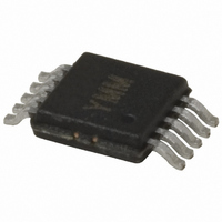
MIC2174-1YMM Micrel Inc, MIC2174-1YMM Datasheet - Page 16

MIC2174-1YMM
Manufacturer Part Number
MIC2174-1YMM
Description
IC BUCK SYNC ADJ 25A 10MSOP
Manufacturer
Micrel Inc
Series
Hyper Speed Control™r
Type
Step-Down (Buck)r
Datasheet
1.MIC2174-1YMM.pdf
(27 pages)
Specifications of MIC2174-1YMM
Internal Switch(s)
No
Synchronous Rectifier
Yes
Number Of Outputs
1
Voltage - Output
0.8 ~ 5.5 V
Frequency - Switching
300kHz
Voltage - Input
3 ~ 5.5 V
Operating Temperature
-40°C ~ 125°C
Mounting Type
Surface Mount
Package / Case
10-MSOP, Micro10™, 10-uMAX, 10-uSOP
Power - Output
421mW
Primary Input Voltage
40V
No. Of Outputs
2
Output Current
25A
Voltage Regulator Case Style
MSOP
No. Of Pins
10
Operating Temperature Range
-40°C To +125°C
Svhc
No SVHC (15-Dec-2010)
Lead Free Status / RoHS Status
Lead free / RoHS Compliant
Current - Output
-
Lead Free Status / RoHS Status
Lead free / RoHS Compliant, Lead free / RoHS Compliant
Other names
576-3546-5
Available stocks
Company
Part Number
Manufacturer
Quantity
Price
Company:
Part Number:
MIC2174-1YMM
Manufacturer:
Micrel Inc
Quantity:
135
Micrel, Inc.
where:
T
T
R
(usually specified by the manufacturer)
Output Capacitor Selection
The type of the output capacitor is usually determined by
its ESR (equivalent series resistance). Voltage and RMS
current capability are two other important factors for
selecting the output capacitor. Recommended capacitors
are tantalum, low-ESR aluminum electrolytic, OS-CON
and POSCAPS. The output capacitor’s ESR is usually
the main cause of the output ripple. The output capacitor
ESR also affects the control loop from a stability point of
view. The maximum value of ESR is calculated:
where:
Δ V
ΔI
The total output ripple is a combination of the ESR and
output capacitance. The total ripple is calculated below:
where:
D = duty cycle
C
f
As described in the “Theory of Operation” subsection in
Functional Description , the MIC2174/MIC2174C requires
at least 20mV peak-to-peak ripple at the FB pin to make
the gm amplifier and the error comparator to behavior
properly. Also, the output voltage ripple should be in
phase with the inductor current. Therefore, the output
voltage ripple caused by the output capacitor C
should be much smaller than the ripple caused by the
output capacitor ESR. If low-ESR capacitors, such as
ceramic
capacitors, a ripple injection method should be applied to
provide the enough FB voltage ripple. Please refer to the
“Ripple Injection” subsection for more details.
SW
September 2010
H
20°C
ΔV
WINDING(20°C)
OUT
L(PP)
OUT(pp)
= temperature of wire under full load
= switching frequency
OUT(pp)
= output capacitance value
= ambient temperature
= peak-to-peak inductor current ripple
= peak-to-peak output voltage ripple
capacitors,
=
ESR
= room temperature winding resistance
⎛
⎜
⎜
⎝
C
C
OUT
OUT
ΔI
≤
×
L(PP)
are
f
ΔV
SW
ΔI
OUT(pp)
L(PP)
×
selected
8
⎞
⎟
⎟
⎠
2
+
(
ΔI
L(PP)
as
×
the
ESR
C
output
OUT
(19)
(20)
OUT
)
2
16
The voltage rating of the capacitor should be twice the
output voltage for a tantalum and 20% greater for
aluminum electrolytic or OS-CON. The output capacitor
RMS current is calculated below:
The power dissipated in the output capacitor is:
Input Capacitor Selection
The input capacitor for the power stage input V
should be selected for ripple current rating and voltage
rating. Tantalum input capacitors may fail when
subjected to high inrush currents, caused by turning the
input supply on. A tantalum input capacitor’s voltage
rating should be at least two times the maximum input
voltage to maximize reliability. Aluminum electrolytic,
OS-CON, and multilayer polymer film capacitors can
handle the higher inrush currents without voltage de-
rating. The input voltage ripple will primarily depend on
the input capacitor’s ESR. The peak input current is
equal to the peak inductor current, so:
The input capacitor must be rated for the input current
ripple. The RMS value of input capacitor current is
determined at the maximum output current. Assuming
the peak-to-peak inductor current ripple is low:
The power dissipated in the input capacitor is:
External Schottky Diode (Optional)
An external freewheeling diode, which is not necessary,
is used to keep the inductor current flow continuous
while both MOSFETs are turned off. This dead-time
prevents current from flowing unimpeded through both
MOSFETs and is typically 30ns. The diode conducts
twice during each switching cycle. Although the average
current through this diode is small, the diode must be
able to handle the peak current.
ΔV
P
I
P
I
CIN(RMS)
C
DISS(CIN)
DISS(C
OUT
IN
(RMS)
= I
OUT
L(pk)
≈
= I
)
=
I
=
OUT(max)
× ESR
CIN(RMS)
ΔI
I
C
L(PP)
12
OUT
(RMS)
CIN
2
×
× ESR
D
2
MIC2174/MIC2174C
×
×
ESR
(1
CIN
M9999-091310-C
−
D)
C
OUT
(21)
(22)
(23)
(24)
(25)
HSD


