L4960H STMicroelectronics, L4960H Datasheet
L4960H
Specifications of L4960H
Available stocks


Related parts for L4960H


L4960H Summary of contents
Page 1
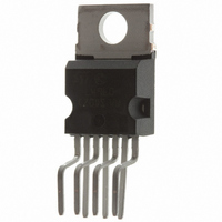
... POWER SWITCHING REGULATOR ORDERING NUMBERS: L4960 (Vertical) The L4960 is mounted in a Heptawatt plastic power package and requires very few external compo- nents. Efficient operation at switching frequencies up to 150KHz allows a reduction in the size and cost of external filter components. L4960 HEPTAWATT L4960H (Horizontal) 1/16 ...
Page 2
L4960 PIN CONNECTION (Top view) ABSOLUTE MAXIMUM RATINGS Symbol V Input voltage Input to output voltage difference Negative output DC voltage 7 Negative output peak voltage 0 ...
Page 3
THERMAL DATA Symbol R Thermal resistance junction-case th j-case R Thermal resistance junction-ambient th j-amb ELECTRICAL CHARACTERISTICS (Refer to the test circuit, T specified) Symbol Parameter DYNAMIC CHARACTERISTICS V Output voltage range o V Input voltage range i V Line ...
Page 4
L4960 ELECTRICAL CHARACTERISTICS (continued) Symbol Parameter DC CHARACTERISTICS I Quiescent drain current 1Q -I Output leakage current 7L SOFT START I Source current 6SO I Sink current 6SI ERROR AMPLIFIER V High level output voltage 3H V Low level output ...
Page 5
CIRCUIT OPERATION (refer to the block diagram) The L4960 is a monolithic stepdown switching regu- lator providing output voltages from 5.1V to 40V and delivering 2.5A. The regulation loop consists of a sawtooth oscilla- tor, error amplifier, comparator and the ...
Page 6
L4960 Figure 3. Test and application circuit C6, C7: EKR (ROE 150 (COGEMA 946042) CORE TYPE: MAGNETICS 58206-A2 MPP Figure 4. Quiescent drain current vs. supply voltage (0% duty cycle) 6/16 N TURNS 45, WIRE ...
Page 7
Figure 7. Quiescent drain current vs. junction tem- perature (100% duty cycle) Figure 10. Open loop fre- quency and phase responde of error amplifier Figure 13. Switching fre- quency vs. R2 (see test circuit) Figure 8. Reference voltage (pin 2) ...
Page 8
L4960 Figure 16. Supply voltage ripple rejection vs. frequency Figure 19. Power dissipation derating curve F igu re 22. Effi ciency vs. output current 8/16 Figure 17. Dropout voltage between pin 1 and pin 7 vs. current at pin 7 ...
Page 9
APPLICATION INFORMATION Figure 24. Typical application circuit EKR (ROE BYW80 OR 5A SCHOTTKY DIODE 1 SUGGESTED INDUCTOR 150 CORE TYPE: MAGNETICS 58206 - ...
Page 10
L4960 APPLICATION INFORMATION Figure 26. A minimal 5.1V fixed regulator; Very few component are required * COGEMA 946042 (TOROID CORE) 969051 (U15 CORE) ** EKR (ROE) Figure 27. Programmable power supply V = 5.1V to 15V 2.5A ...
Page 11
APPLICATION INFORMATION (continued) Figure 28. Microcomputer supply with + 5.1V, -5V, +12V and -12V outputs L4960 11/16 ...
Page 12
L4960 APPLICATION INFORMATION (continued) Figure 29. DC-DC converter 5.1V/4A, 12V/2.5A; a suggestion how to synchronize a negative output L1 COGEMA 946042 (969051 COGEMA 946044 (946045 BYW80 Figure ...
Page 13
APPLICATION INFORMATION (continued) Figure 31. Regulator for distributed supplies MOUNTING INSTRUCTION The power dissipated in the circuit must be removed by adding an external heatsink. Thanks to the Heptawatt package attaching the hetsink is very simple, a screw or a ...
Page 14
L4960 mm DIM. MIN. TYP. MAX. A 4.8 C 1.37 D 2.4 2.8 0.094 D1 1.2 1.35 0.047 E 0.35 0.55 0.014 E1 0.7 0.97 0.028 F 0.6 0.8 0.024 F1 0.9 G 2.34 2.54 2.74 0.095 G1 4.88 5.08 ...
Page 15
DIM. MIN. TYP. MAX. MIN. A 4.8 C 1.37 D 2.4 2.8 0.094 D1 1.2 1.35 0.047 E 0.35 0.55 0.014 F 0.6 0.8 0.024 F1 0.9 G 2.41 2.54 2.67 0.095 G1 4.91 5.08 5.21 0.193 G2 7.49 ...
Page 16
... No license is granted by implication or otherwise under any patent or patent rights of STMicroelectronics. Specification mentioned in this publication are subject to change without notice. This publication supersedes and replaces all information previously supplied. STMicroelectronics products are not authorized for use as critical components in life support devices or systems without express written approval of STMicroelectronics. © ...