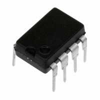
LM2578AN/NOPB National Semiconductor, LM2578AN/NOPB Datasheet - Page 17

LM2578AN/NOPB
Manufacturer Part Number
LM2578AN/NOPB
Description
IC REG SIMPLE SWITCHER 8-DIP
Manufacturer
National Semiconductor
Type
Step-Down (Buck), Step-Up (Boost), Inverting, Flybackr
Datasheet
1.LM3578AMNOPB.pdf
(20 pages)
Specifications of LM2578AN/NOPB
Internal Switch(s)
Yes
Synchronous Rectifier
No
Number Of Outputs
1
Current - Output
750mA
Frequency - Switching
20kHz
Voltage - Input
2 ~ 40 V
Operating Temperature
-40°C ~ 85°C
Mounting Type
Through Hole
Package / Case
8-DIP (0.300", 7.62mm)
No. Of Outputs
1
Output Voltage
1V
Output Current
750mA
No. Of Pins
8
Operating Temperature Range
-40°C To +85°C
Msl
MSL 1 - Unlimited
Input Voltage
40V
Input Voltage Primary Max
40V
Rohs Compliant
Yes
Primary Input Voltage
40V
Lead Free Status / RoHS Status
Lead free / RoHS Compliant
Voltage - Output
-
Power - Output
-
Other names
*LM2578AN
*LM2578AN/NOPB
LM2578AN
*LM2578AN/NOPB
LM2578AN
Typical Applications
where:
RS-232 LINE DRIVER POWER SUPPLY
The power supply, shown in Figure 23, operates from an
input voltage as low as 4.2V (5V nominal), and delivers an
output of
The circuit provides a load regulation of
to 100% of full load) and a line regulation of
notable features include a cycle-by-cycle current limit and an
output voltage ripple of less than 40 mVp-p.
A unique feature of this circuit is its use of feedback from
both outputs. This dual feedback configuration results in a
sharing of the output voltage regulation by each output so
that neither side becomes unbalanced as in single feedback
systems. In addition, since both sides are regulated, it is not
necessary to use a linear regulator for output regulation.
The feedback resistors, R2 and R3, may be selected as
follows by assuming a value of 10 kΩ for R1;
R2 = (V
R3 = (|V
Actually, the currents used to program the values for the
feedback resistors may vary from 40 µA to 60 µA, as long as
their sum is equal to the 100 µA necessary to establish the
1V threshold across R1. Ideally, these currents should be
equal (50 µA each) for optimal control. However, as was
done here, they may be mismatched in order to use standard
resistor values. This results in a slight mismatch of regulation
between the two outputs.
The current limit resistor, R4, is selected by dividing the
current limit threshold voltage by the maximum peak current
level in the output switch. For our purposes R4 = 110 mV/
750 mA = 0.15Ω. A value of 0.1Ω was used.
o
o
| +1V)/54.2 µA = 240 kΩ
− 1V)/45.8 µA = 240 kΩ
±
12V at
±
40 mA with better than 70% efficiency.
(Continued)
±
150 mV (from 10%
±
10 mV. Other
17
Capacitor C1 sets the oscillator frequency and is selected
from Figure 1.
Capacitor C2 serves as a compensation capacitor for syn-
chronous operation and a value of 10 to 50 pF should be
sufficient for most applications.
FIGURE 23. RS-232 Line Driver Power Supply
9V ≤ V
V
I
V
f
R1 = 110k
R2 = 10k
R3 = 0.15
R4 = 220k
V
V
I
f
R1 = 10 kΩ
R2 = 240 kΩ
R3 = 240 kΩ
o
osc
o
osc
o
ripple
in
o
= 100 mA
=
= 12V
±
= 5V
= 50 kHz
= 80 kHz
FIGURE 22. Buck-Boost Regulator
±
12V
40 mA
= 50 mV
in
≤ 15V
R5 = 270
C1 = 1820 pF
C2 = 220 µF
C3 = 20 pF
C4 = 0.0022 µF
L1 = 220 µH
D1, D2 = 1N5819
Q1 = D44
R4 = 0.15Ω
C1 = 820 pF
C2 = 10 pF
C3 = 220 µF
D1, D2, D3 = 1N5819
T1 = PE-64287
www.national.com
00871114
00871113


