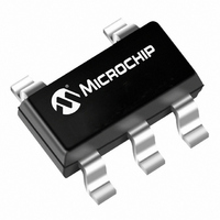
TC105503ECTTR Microchip Technology, TC105503ECTTR Datasheet - Page 4

TC105503ECTTR
Manufacturer Part Number
TC105503ECTTR
Description
IC PFM/PWM CONTRLLER 5V SOT23A-5
Manufacturer
Microchip Technology
Type
Step-Down (Buck)r
Specifications of TC105503ECTTR
Internal Switch(s)
No
Synchronous Rectifier
No
Number Of Outputs
1
Voltage - Output
5V
Current - Output
1A
Frequency - Switching
300kHz
Voltage - Input
0.9 ~ 2.2 V
Operating Temperature
-40°C ~ 85°C
Mounting Type
Surface Mount
Package / Case
SOT-23-5, SC-74A, SOT-25
Power - Output
150mW
Output Current
100 mA
Mounting Style
SMD/SMT
Lead Free Status / RoHS Status
Lead free / RoHS Compliant
Available stocks
Company
Part Number
Manufacturer
Quantity
Price
Part Number:
TC105503ECTTR
Manufacturer:
MICROCHIP/微芯
Quantity:
20 000
TC105
DS21349B-page 4
3.0
The TC105 is a PFM/PWM step-down DC/DC
controller for use in systems operating from two or
more cells, or in line-powered applications. It uses
PWM as the primary modulation scheme, but automat-
ically converts to PFM at output duty cycles less than
approximately 10%. The conversion to PFM provides
reduced supply current, and therefore higher operating
efficiency at low loads. The TC105 uses an external
switching transistor, allowing construction of switching
regulators with output currents of up to 1A.
The TC105 consumes only 102µA, max, of supply
current when V
placed in a 0.5µA shutdown mode by bringing the
shutdown input (SHDN) low. The regulator remains
disabled while in shutdown mode, and output voltage
discharges to zero through the load. Normal operation
resumes when SHDN is brought high. Other features
include a built-in undervoltage lockout (UVLO) and
externally programmable soft start time.
3.1
The TC105 enters a low power shutdown mode when
SHDN is brought low. While in shutdown, the oscillator
is disabled and the output switch is shut off. Normal
regulator operation resumes when SHDN is again
brought high. SHDN may be tied to the input supply if
not used.
3.2
Soft start allows the output voltage to gradually ramp
from 0 to rated output value during start-up. This action
minimizes (or eliminates) overshoot, and in general,
reduces stress on circuit components. Figure 4-1
shows the circuit required to implement soft start
(values of 470K and 0.033µF for R
respectively, are adequate for most applications).
3.3
The TC105 is disabled when V
voltage lockout threshold. This threshold is equal to the
guaranteed minimum operating voltage for the TC105
(i.e., 2.2V). When UVLO is active, the TC105 is
completely disabled.
DETAILED DESCRIPTION
Low Power Shutdown Mode
Soft Start
Undervoltage Lockout (UVLO)
IN
= 5V and V
OUT
IN
is below the under-
= 3.3V, and can be
SS
and C
SS
3.4
Using an input bypass capacitor reduces peak current
transients drawn from the input supply and reduces the
switching noise generated by the regulator. The source
impedance of the input supply determines the size of
the capacitor that should be used.
3.5
The effective series resistance of the output capacitor
directly affects the amplitude of the output voltage
ripple. (The product of the peak inductor current and
the ESR determines output ripple amplitude.) There-
fore, a capacitor with the lowest possible ESR should
be selected. Smaller capacitors are acceptable for light
loads or in applications where ripple is not a concern.
The Sprague 595D series of tantalum capacitors are
among the smallest of all low ESR surface mount
capacitors
components and suppliers.
3.6
Selecting the proper inductor value is a trade-off
between physical size and power conversion require-
ments. Lower value inductors cost less, but result in
higher ripple current and core losses. They are also
more prone to saturate since the coil current ramps
faster and could overshoot the desired peak value. This
not only reduces efficiency, but could also cause the
current rating of the external components to be
exceeded. Larger inductor values reduce both ripple
current and core losses, but are larger in physical size
and tend to increase the start-up time slightly.
A 22µH inductor is recommended as the best overall
compromise. For highest efficiency, use inductors with
a low DC resistance (less than 20 mΩ). To minimize
radiated noise, consider using a toroid, pot core or
shielded-bobbin inductor.
3.7
The high operating frequency of the TC105 requires a
high-speed diode. Schottky diodes such as the MA737
or 1N5817 through 1N5823 (and the equivalent surface
mount versions) are recommended. Select a diode
whose average current rating is greater than the peak
inductor current and whose voltage rating is higher
than V
DD
Input Bypass Capacitors
Output Capacitor
Inductor Selection
Output Diode
MAX
.
available.
©
Table 4-1
2002 Microchip Technology Inc.
lists
suggested


