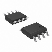
AP1580SL-13 Diodes Inc, AP1580SL-13 Datasheet - Page 3

AP1580SL-13
Manufacturer Part Number
AP1580SL-13
Description
IC BUCK CONVERTER 3A 8-SOIC
Manufacturer
Diodes Inc
Type
Step-Down (Buck)r
Datasheet
1.AP1580SL-13.pdf
(9 pages)
Specifications of AP1580SL-13
Internal Switch(s)
Yes
Synchronous Rectifier
No
Number Of Outputs
1
Voltage - Output
0.8 ~ 36 V
Current - Output
3A
Frequency - Switching
300kHz
Voltage - Input
10 ~ 40 V
Operating Temperature
-25°C ~ 85°C
Mounting Type
Surface Mount
Package / Case
8-SOIC (3.9mm Width)
Lead Free Status / RoHS Status
Lead free / RoHS Compliant
Power - Output
-
Lead Free Status / Rohs Status
Lead free / RoHS Compliant
Absolute Maximum Ratings
Caution:
Recommended Operating Conditions
Electrical Characteristics
Notes:
AP1580 Rev. 2
∆V
∆V
Symbol
Symbol
V
R
Symbol
OUT
OUT
V
I
f
I
OUTPUT
Top
f
V
V
V
DC
DS(ON)
V
STBY
OSC1
θ
T
V
V
V
LIMIT
θ
I
OSC
I
boost
SH
η
SL
JC
CC
I
FB
JA
FB
EN
ST
V
IN
IH
IL
T
/V
/V
4. Devices mounted on 2oz copper, minimum recommended pad layout, FR-4 PCB.
OUT
3. The PCB layout copper area should be much greater than 10*10mm at the Vcc pins (5&6) of the AP1580, if you need large PD or low Tc&T
IN
The absolute maximum ratings are rated values exceeding which the product could suffer physical damage. These values must therefore not
A
be exceeded under any conditions.
OUT
OUT
The dual Vcc pins (5&6) on the SOP-8L package are internally connected.
Feedback Voltage
Input Voltage
Standby Current
Line Regulation
Load Regulation
Oscillation Frequency
Frequency of Current Limit or
Short Circuit Protect
Maximum Duty Cycle
Minimum Duty Cycle
EN Pin Logic Input Threshold
Voltage
EN Pin Input Leakage Current
Internal MOSFET R
Current Limit
Efficiency
Thermal Resistance
Junction-to-Ambient (Note 4)
Thermal Resistance
Junction-to-Case (Note 4)
V
V
EN Pin Voltage
V
Switch Pin Voltage
Operating Junction Temperature Range
Storage Temperature Range
CC
OUT
boost
Pin Voltage
Input Voltage
Output Current
Operating Ambient Temperature
Pin Voltage
Pin Voltage
Parameter
DS(ON)
Parameter
NOT RECOMMENDED FOR NEW
Parameter
(V
IN
= 12V, T
DESIGN, USE AP5004
www.diodes.com
V
V
I
Measure waveform at SW pin
Measure waveform at SW pin
V
V
Regulator ON
Regulator OFF
V
OUT
EN
IN
FB
FB
IN
PWM CONTROL 3A STEP-DOWN CONVERTER
= 10V~40V
= 12V, V
= 0.1 to 3A
=0.5V
=1.0V
=0V
3 of 9
A
=25°C, unless otherwise specified)
Conditions
OUT
= 5V, I
OUT
= 3A
Min
-25
V
V
10
V
0
SS
SS
SS
V
- 0.3 to V
- 0.3 to V
V
- 0.3 to V
SS
-25 to +125
-40 to +150
0.780
OUTPUT
Min.
240
2.0
- 0.3 to V
Rating
10
--
4
-
-
-
-
-
-
-
-
-
-
-
-
Max
+ 5V
40
85
CC
CC
3
SS
Typ.
±1.0
±0.8
13.4
300
149
0.8
-10
4.5
30
90
20
80
90
+ 0.3
+ 0.3
+ 45
0
CC
-
-
-
-
©
AP1580
Diodes Incorporated
0.820
Max.
±1.5
360
120
0.8
July 2008
40
±1
2
-
-
-
-
-
-
-
-
-
-
Unit
o
V
A
C
Unit
o
o
o
o
V
V
V
V
V
Unit
KHz
KHz
C
C
mΩ
C/W
C/W
µA
µA
µA
%
%
%
%
%
V
V
V
A
A
.


