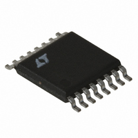
LT3430EFE-1#TRPBF Linear Technology, LT3430EFE-1#TRPBF Datasheet - Page 25

LT3430EFE-1#TRPBF
Manufacturer Part Number
LT3430EFE-1#TRPBF
Description
IC BUCK SYNC ADJ 3A 16TSSOP
Manufacturer
Linear Technology
Type
Step-Down (Buck)r
Datasheet
1.LT3430EFE-1PBF.pdf
(28 pages)
Specifications of LT3430EFE-1#TRPBF
Internal Switch(s)
Yes
Synchronous Rectifier
No
Number Of Outputs
1
Voltage - Output
1.2 ~ 54 V
Current - Output
3A
Frequency - Switching
100kHz
Voltage - Input
5.5 ~ 60 V
Operating Temperature
-40°C ~ 125°C
Mounting Type
Surface Mount
Package / Case
16-TSSOP Exposed Pad, 16-eTSSOP, 16-HTSSOP
Lead Free Status / RoHS Status
Lead free / RoHS Compliant
Power - Output
-
Available stocks
Company
Part Number
Manufacturer
Quantity
Price
APPLICATIONS INFORMATION
INDUCTOR VALUE
The criteria for choosing the inductor is typically based on
ensuring that peak switch current rating is not exceeded.
This gives the lowest value of inductance that can be
used, but in some cases (lower output load currents) it
may give a value that creates unnecessarily high output
ripple voltage.
The diffi culty in calculating the minimum inductor size
needed is that you must fi rst decide whether the switcher
will be in continuous or discontinuous mode at the critical
point where switch current reaches 3A. The fi rst step is to
use the following formula to calculate the load current above
which the switcher must use continuous mode. If your
load current is less than this, use the discontinuous mode
formula to calculate minimum inductor needed. If load
current is higher, use the continuous mode formula.
Output current where continuous mode is needed:
Minimum inductor discontinuous mode:
** MAXIMUM LOAD CURRENT DEPENDS ON MINIMUM INPUT VOLTAGE
5.5V TO
* INCREASE L1 FOR HIGHER CURRENT APPLICATIONS.
INPUT
I
L
SEE APPLICATIONS INFORMATION
CONT
AND INDUCTOR SIZE. SEE APPLICATIONS INFORMATION
44V
MIN
4.7µF
100V
CER
C3
=
>
Figure 15. Positive-to-Negative Converter
2
(
V
4
V
OUT
( )( )
IN
GND
(
f I
V
IN
C
LT3430
BOOST
F
P
)(
+
I
OUT
2
V
OUT
V
V
C
(
SW
)
FB
V
R
C
IN
C
)(
C
) ( )
V
2
IN
I
P
MMSD914TI
D1
30BQ060
+
C2
0.68µF
2
V
D2
OUT
†
10µH
L1*
+
R2
4.12k
36.5k
D4
7V
V
R1
F
)
+
30BQ015
C1
100µF
16V TANT
OUTPUT**
–12V, 0.5A
D3
3430 F15
Minimum inductor continuous mode:
For a 40V to –12V converter using the LT3430/LT3430-
1 with peak switch current of 3A and a catch diode of
0.52V:
For a load current of 0.5A, this says that discontinuous
mode can be used and the minimum inductor needed is
found from:
In practice, the inductor should be increased by about
30% over the calculated minimum to handle losses and
variations in value. This suggests a minimum inductor of
10µH for this application.
Ripple Current in the Input and Output Capacitors
Positive-to-negative converters have high ripple current in
the input capacitor. For long capacitor lifetime, the RMS
value of this current must be less than the high frequency
ripple current rating of the capacitor. The following formula
will give an approximate value for RMS ripple current. This
formula assumes continuous mode and large inductor
value. Small inductors will give somewhat higher ripple
current, especially in discontinuous mode. The exact for-
mulas are very complex and appear in Application Note
44, pages 29 and 30. For our purposes here I have simply
added a fudge factor (ff). The value for ff is about 1.2 for
higher load currents and L ≥15µH. It increases to about
2.0 for smaller inductors at lower load currents.
ff = 1.2 to 2.0
The output capacitor ripple current for the positive-to-
negative converter is similar to that for a typical buck
regulator—it is a triangular waveform with peak-to-peak
I
L
L
Capacitor I
CONT
MIN
MIN
=
=
=
2
(
200 10 3
( )(
f V
4 40 12 40 12 0 52
2 12 0 5
RMS
( )( . )
(
•
IN
+
+
= ( )(
3
V
)( )
ff I
OUT
( ) ( )
40 3
)(
LT3430/LT3430-1
2
OUT
2
)
=
⎡
⎢
⎣
(
+
I
V
P
6 7
IN
)
2
.
–
)(
I
µ
V
+
OUT
V
V
OUT
H
OUT
IN
. )
⎛
⎜
⎝
1
)
+
=
(
V
1 148
OUT
.
V
IN
+
A
25
V
F
34301fa
)
⎞
⎟
⎠
⎤
⎥
⎦


