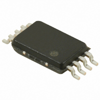
S-8341A30AFT-T2-G Seiko Instruments, S-8341A30AFT-T2-G Datasheet - Page 22

S-8341A30AFT-T2-G
Manufacturer Part Number
S-8341A30AFT-T2-G
Description
IC REG SW 600KHZ 3.0V 8-TSSOP
Manufacturer
Seiko Instruments
Type
Step-Up (Boost)r
Datasheet
1.S-8340A25AFT-T2-G.pdf
(55 pages)
Specifications of S-8341A30AFT-T2-G
Internal Switch(s)
No
Synchronous Rectifier
No
Number Of Outputs
1
Voltage - Output
3V
Frequency - Switching
600kHz
Voltage - Input
0.9 ~ 6 V
Operating Temperature
-40°C ~ 85°C
Mounting Type
Surface Mount
Package / Case
8-TSSOP
Power - Output
300mW
Output Voltage
3 V
Operating Temperature Range
- 40 C to + 85 C
Mounting Style
SMD/SMT
Lead Free Status / RoHS Status
Lead free / RoHS Compliant
Current - Output
-
Lead Free Status / Rohs Status
Lead free / RoHS Compliant
22
STEP-UP, 600 kHz, PWM CONTROL OR PWM/PFM SWITCHABLE SWITCHING REGULATOR CONTROLLER
S-8340/8341 Series
2. Inductor
3. Diode
4. Capacitors (C
The inductance value (L value) greatly affects the maximum output current (I
As the L value is reduced gradually, the peak current (I
even smaller, I
As the L value is increased, the dissipation in the switching transistor due to I
reaches the maximum at a certain L value. As the L value is made even larger, the efficiency degrades since the
dissipation due to the series resistance of the inductor increases. I
In the S-8340/8341 Series, as the L value is increased, the output voltage may be unstable depending on the
conditions of the input voltage, output voltage, and load current. Select the L value after performing a thorough
valuation under actual use conditions. The guidelines for the L range are from 2.2 to 22 μH for the A and B types,
and 4.7 to 47 μH for the C and D types.
The recommended L value is 5 to 10 μH for the A and B types, and 10 to 22 μH for the C and D types.
When choosing an inductor, attention to its allowable current should be paid since the current exceeding the
allowable value will cause magnetic saturation in the inductor, leading to a marked decline in efficiency and a
breakdown of the IC due to large current.
An inductor should therefore be selected so that I
the following equations in non-continuous operation mode.
Where f
the diode. V
For example, if a power supply with the input voltage (V
= 30 mA is used, f
155 mA from the above formula. Therefore, in this case, an inductor with a permissible current of 155 mA or higher
for the L value of 10 μH should be selected.
Use an external diode that meets the following requirements :
A capacitor inserted on the input side (C
the input current. Select a C
100 μF is recommended for a capacitance depending on the impedance of the power source and load current
value.
For the output side capacitor (C
smoothing the ripple voltage. When the input voltage is extremely high or the load current is extremely large, the
output voltage may become unstable. In this case the unstable area will become narrow by selecting a large
capacitance for an output capacitor. A tantalum electrolyte capacitor is recommended since the unstable area
widens when a capacitor with a large ESR, such as an aluminum electrolyte capacitor, or a capacitor with a small
ESR, such as a ceramic capacitor, is chosen.
It is recommended that a capacitor of which the capacitance is 47 to 200 μF and ESR is 40 to 270 mΩ be selected.
Fully evaluate input and output capacitors under actual operating conditions, then select them.
Low forward voltage (Schottky barrier diode is recommended.)
High switching speed (50 ns max.)
The reverse-direction withstand voltage is V
The current rating is I
OSC
is the oscillation frequency, L is the inductance value of the inductor, and V
F
IN
OUT
should be appropriately 0.4 V.
I
PK
, C
=
decreases since the efficiency degrades and the current driveability is insufficient.
OSC
L
)
2 I
= 600 kHz when the S-8340A50AFT is used. When 10 μH is selected for the L value, I
×
OUT
PK
or larger.
×
IN
fosc
(
V
value according to the impedance of the power supply used. Approximately 47 to
OUT
L
), select a large capacitance with low ESR (Equivalent Series Resistance) for
×
+
L
V
F
IN
−
) improves the efficiency by reducing the power impedance and stabilizing
V
IN
Seiko Instruments Inc.
)
OUT
PK
+ V
does not surpass its allowable current. I
F
IN
PK
or higher.
) = 3 V, output voltage (V
) increases and I
OUT
also decreases.
OUT
OUT
) and the efficiency (η).
increases. As the L value is made
OUT
PK
decreases, and the efficiency
) = 5 V, and load current (I
F
is the forward voltage of
PK
is represented by
Rev.4.0
_00
OUT
PK
=
)


