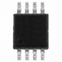
L6920DBTR STMicroelectronics, L6920DBTR Datasheet

L6920DBTR
Specifications of L6920DBTR
Available stocks
Related parts for L6920DBTR
L6920DBTR Summary of contents
Page 1
Introduction The L6920DB is a high efficiency monolithic step-up switching converter IC especially designed for battery powered applications, thanks to its minimum start-up of 0.8 V, and a minimum operating voltage of 0 requires only three external components ...
Page 2
Contents Contents 1 Application information . . . . . . . . . . . . . . . . . . . . . . . . . . . . . . . . . . . ...
Page 3
AN2206 1 Application information Figure 1. L6920DB Example of overall application size Figure 2. Application circuit V =2.5V BATT Figure 3. Pin connections (top view 10µH C1 47µF L6920D V REF 4 C4 100nF 6 GND Application ...
Page 4
Application information 1.1 Output voltage selection The output voltage must be selected by configuring the FB pin. Three choices are available: ● fixed 3.3 V ● fixed 5 V ● adjustable output set via an external resistor divider. R4 and ...
Page 5
AN2206 Table 2. Distributor's capacitor main list (continued) Manufacturer PANASONIC SANYO POSCAP 1.4 Inductor selection Usually, inductors ranging between 2 µ µH satisfy most application requirements. However, small-value inductors are physically smaller and guarantee a faster response to ...
Page 6
Application information If a Low battery voltage detection than 1. required possible using a resistor divider between V In this case the relationship is the following: Equation 2 In order to keep the efficiency high, the ...
Page 7
AN2206 Table 4. Demo board components description (continued) Name Table 5. Jumper connections Jumper J1 J2 1.7 Layout guidelines The board layout is very important in order to minimize noise, high ...
Page 8
Application information Figure 6. Demoboard layout (top view) Figure 7. Demoboard layout (bottom view) 8/11 AN2206 ...
Page 9
AN2206 2 Typical performance Figure 8. Efficiency vs. output current at Vout = 3.3 V Figure 9. Efficiency vs. output current at Vout = 5 V Figure 10. Start-up voltage vs. output current at Vout = 5 V VStart up ...
Page 10
Revision history Figure 11. Start-up voltage vs. output current at Vout = 3 Revision history Table 6. Revision history Date 05-Dec-2005 09-Feb-2006 05-Oct-2006 26-Mar-2007 10/11 VStart up vs. output current 1600 V out=3.3V 1500 1400 1300 1200 1100 ...
Page 11
... AN2206 Information in this document is provided solely in connection with ST products. STMicroelectronics NV and its subsidiaries (“ST”) reserve the right to make changes, corrections, modifications or improvements, to this document, and the products and services described herein at any time, without notice. All ST products are sold pursuant to ST’s terms and conditions of sale. ...


