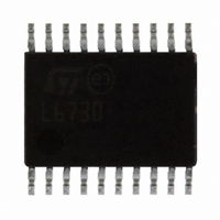
L6730B STMicroelectronics, L6730B Datasheet - Page 34

L6730B
Manufacturer Part Number
L6730B
Description
IC CTRLR ADJ STPDN SYNC 20-TSSOP
Manufacturer
STMicroelectronics
Type
Step-Down (Buck)r
Datasheet
1.L6730TR.pdf
(52 pages)
Specifications of L6730B
Internal Switch(s)
No
Synchronous Rectifier
Yes
Number Of Outputs
1
Voltage - Output
Adj to 0.6V
Frequency - Switching
100kHz ~ 1MHz
Voltage - Input
1.8 ~ 14 V
Operating Temperature
-40°C ~ 85°C
Mounting Type
Surface Mount
Package / Case
20-TSSOP Exposed Pad, 20-eTSSOP, 20-HTSSOP
Output Voltage
0.6 V
Input Voltage
1.8 V to 14 V
Maximum Operating Temperature
+ 85 C
Minimum Operating Temperature
- 40 C
Package
HTSSOP20
For Use With
497-5868 - EVAL BOARD 30A 400KHZ L6730497-5501 - EVAL BOARD FOR L6730XX
Lead Free Status / RoHS Status
Lead free / RoHS Compliant
Current - Output
-
Power - Output
-
Lead Free Status / Rohs Status
Lead free / RoHS Compliant
Available stocks
Company
Part Number
Manufacturer
Quantity
Price
Company:
Part Number:
L6730BTR
Manufacturer:
STM
Quantity:
3 172
Application details
6.2
6.3
34/52
Output capacitors
The output capacitors are basic components for the fast transient response of the power
supply. They depend on the output voltage ripple requirements, as well as any output
voltage deviation requirement during a load transient. During a load transient, the output
capacitors supply the current to the load or absorb the current stored into the inductor until
the converter reacts. In fact, even if the controller recognizes immediately the load transient
and sets the duty cycle at 100% or 0%, the current slope is limited by the inductor value. The
output voltage has a first drop due to the current variation inside the capacitor (neglecting
the effect of the ESL):
Moreover, there is an additional drop due to the effective capacitor discharge or charge that
is given by the following formulas:
Formula (8) is valid in case of positive load transient while the formula (9) is valid in case of
negative load transient. D
For a given inductor value, minimum input voltage, output voltage and maximum load
transient, a maximum ESR, and a minimum C
values also affect the static output voltage ripple. In the worst case the output voltage ripple
can be calculated with the following formula:
Usually the voltage drop due to the ESR is the biggest one while the drop due to the
capacitor discharge is almost negligible.
Input capacitors
The input capacitors have to sustain the RMS current flowing through them, that is:
Where D is the duty cycle. The equation reaches its maximum value, I
The losses in worst case are:
Δ
Vout
Δ
COUT
Vout
MAX
Δ
=
Vout
=
2
Irms
is the maximum duty cycle value that in the L6730/B is 100%.
Doc ID 11938 Rev 3
Δ
⋅
P
Δ
Cout
COUT
Vout
I
=
L
=
⋅
ESR
(
Iout
=
⋅
ESR
ESR
(
Vin
2
⋅
⋅
Δ
⋅
Δ
Cout
0 (
=
Iout
,
+
Iout
min
D
5 .
Δ
8
⋅
Iout
⋅
⋅
2
⋅
1 ( D
OUT
Cout
2
Iout
Vout
⋅
⋅
⋅
D
−
L
L
1
max
⋅
value can be set. The ESR and C
)
)
ESR
⋅
2
Fsw
−
(9)
(11)
(12)
Vout
)
(7)
)
(10)
(8)
OUT
/2 with D = 0.5.
L6730 - L6730B
OUT


