L4962E/A STMicroelectronics, L4962E/A Datasheet - Page 5
L4962E/A
Manufacturer Part Number
L4962E/A
Description
IC REG SW 1.5A VERT 7-HEPTAWATT
Manufacturer
STMicroelectronics
Type
Step-Down (Buck)r
Datasheet
1.L4962A.pdf
(16 pages)
Specifications of L4962E/A
Internal Switch(s)
Yes
Synchronous Rectifier
No
Number Of Outputs
1
Voltage - Output
5.1 ~ 40 V
Current - Output
1.5A
Frequency - Switching
100kHz
Voltage - Input
9 ~ 46 V
Operating Temperature
0°C ~ 125°C
Mounting Type
Through Hole
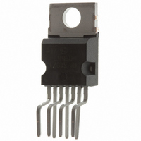
Package / Case
Heptawatt-7 (Vertical, Bent and Staggered Leads)
Power - Output
15W
Output Voltage
40 V
Output Current
1.5 A
Input Voltage
9 V to 46 V
Switching Frequency
85 KHz to 115 KHz
Operating Temperature Range
- 40 C to + 150 C
Mounting Style
Through Hole
Duty Cycle (max)
100 %
Lead Free Status / RoHS Status
Lead free / RoHS Compliant
Other names
497-2943-5
Available stocks
Company
Part Number
Manufacturer
Quantity
Price

Part Number:
L4962E/A
Manufacturer:
ST
Quantity:
20 000


CIRCUIT OPERATION (refer to the block diagram)
The L4962 is a monolithic stepdown switching regu-
lator providing output voltages from 5.1V to 40V and
delivering 1.5A.
The regulation loop consists of a sawtooth oscilla-
tor, error amplifier, comparator and the output
stage. An error signal is produced by comparing the
output voltage with a precise 5.1V on-chip refer-
ence (zener zap trimmed to
This error signal is then compared with the sawtooth
signal to generate the fixed frequency pulse width
modulated pulses which drive the output stage.
The gain and frequency stability of the loop can be
adjusted by an external RC network connected to
pin 11. Closing the loop directly gives an output
voltage of 5.1V. Higher voltages are obtained by
inserting a voltage divider.
Output overcurrents at switch on are prevented by
the soft start function. The error amplifier output is
initially clamped by the external capacitor C
Figure 1. Soft start waveforms
Figure 2. Current limiter waveforms
2%).
ss
and
allowed to rise, linearly, as this capacitor is charged
by a constant current source. Output overload pro-
tection is provided in the form of a current limiter.
The load current is sensed by an internal metal
resistor connected to a comparator. When the load
current exceeds a preset threshold this comparator
sets a flip flop which disables the output stage and
discharges the soft start capacitor. A second com-
parator resets the flip flop when the voltage across
the soft start capacitor has fallen to 0.4V.
The output stage is thus re-enabled and the output
voltage rises under control of the soft start network.
If the overload condition is still present the limiter
will trigger again when the threshold current is
reached. The average short circuit current is limited
to a safe value by the dead time introduced by the
soft start network. The thermal overload circuit dis-
ables circuit operation when the junction tempera-
ture reaches about 150 C and has hysteresis to
prevent unstable conditions.
L4962
5/16
Related parts for L4962E/A
Image
Part Number
Description
Manufacturer
Datasheet
Request
R

Part Number:
Description:
IC REG PWR SW 1.5A 16-POWERDIP
Manufacturer:
STMicroelectronics
Datasheet:

Part Number:
Description:
STMicroelectronics [RIPPLE-CARRY BINARY COUNTER/DIVIDERS]
Manufacturer:
STMicroelectronics
Datasheet:
Part Number:
Description:
STMicroelectronics [LIQUID-CRYSTAL DISPLAY DRIVERS]
Manufacturer:
STMicroelectronics
Datasheet:

Part Number:
Description:
BOARD EVAL FOR MEMS SENSORS
Manufacturer:
STMicroelectronics
Datasheet:
Part Number:
Description:
NPN TRANSISTOR POWER MODULE
Manufacturer:
STMicroelectronics
Datasheet:
Part Number:
Description:
TURBOSWITCH ULTRA-FAST HIGH VOLTAGE DIODE
Manufacturer:
STMicroelectronics
Datasheet:
Part Number:
Description:
Manufacturer:
STMicroelectronics
Datasheet:
Part Number:
Description:
DIODE / SCR MODULE
Manufacturer:
STMicroelectronics
Datasheet:
Part Number:
Description:
DIODE / SCR MODULE
Manufacturer:
STMicroelectronics
Datasheet: