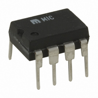
MIC3172YN Micrel Inc, MIC3172YN Datasheet - Page 18

MIC3172YN
Manufacturer Part Number
MIC3172YN
Description
IC REG SW 100KHZ 1.25A 8-DIP
Manufacturer
Micrel Inc
Type
Step-Down (Buck), Step-Up (Boost), Inverting, Cukr
Specifications of MIC3172YN
Internal Switch(s)
Yes
Synchronous Rectifier
No
Number Of Outputs
1
Current - Output
1.25A
Frequency - Switching
100kHz
Voltage - Input
3 ~ 40 V
Operating Temperature
-40°C ~ 85°C
Mounting Type
Through Hole
Package / Case
8-DIP (0.300", 7.62mm)
Power - Output
302mW
Primary Input Voltage
40V
No. Of Outputs
1
Output Current
3A
No. Of Pins
8
Operating Temperature Range
-40°C To +85°C
Supply Voltage Range
3V To 40V
Termination Type
Through Hole
Lead Free Status / RoHS Status
Lead free / RoHS Compliant
Voltage - Output
-
Lead Free Status / RoHS Status
Lead free / RoHS Compliant, Lead free / RoHS Compliant
Other names
576-2255
MIC3172YN
MIC3172YN
mutual coupling to the feedback winding further reduces
primary current eventually turning Q1 off. The primary
windings now change state with the feedback winding
forcing Q2 on repeating the alternate half cycle exactly
as with Q1. This action produces a sinusoidal voltage
wave form; whose amplitude is proportional to the input
voltage, across T1’s primary winding which is stepped
up and capacitively coupled to the lamp.
Lamp Current Regulation
Initial ionization (lighting) of the fluorescent lamp
requires several times the ac voltage across it than is
required to sustain current through the device. The
current through the lamp is sampled and regulated by
the MIC3172 to achieve a given intensity. The MIC3172
uses L1 to maintain a constant average current through
the transistor emitters. This current controls the voltage
amplitude of the Royer oscillator and maintains the lamp
current. During the negative half cycle, lamp current is
rectified by D3. During the positive half cycle, lamp
current is rectified by D2 through R4 and R5. R3 and C5
filter the voltage dropped across R4 and R5 to the
MIC3172’s feedback pin. The MIC3172 maintains a
Micrel
April 2006
Figure 13. Step-Down or Buck Regulator
18
constant lamp current by adjusting its duty cycle to keep
the feedback voltage at 1.24V. The intensity of the lamp
is adjusted using potentiometer R5. The MIC3172
adjusts its duty cycle accordingly to bring the average
voltage across R4 and R5 back to 1.24V.
On/Off Control
Especially important for battery powered applications,
the lamp can be remotely or automatically turned off
using the MIC3172’s EN pin. The entire circuit draws
less than 1µA while shutdown.
Efficiency
To obtain maximum circuit efficiency careful selection of
Q1 and Q2 for low collector to emitter saturation voltage
is a must. Inductor L1 should be chosen for minimal core
and copper losses at the switching frequency of the
MIC3172, and T1 should be carefully constructed from
magnetic materials optimized for the output power
required at the Royer oscillator frequency. Suitable
inductors may be obtained from Coiltronics, Inc., tel:
(407) 241-7876.
MIC2172/3172
(408) 955-1690
M9999-041806


